If you have purchased PCB’s and are still constructing your kx-Amplifier, I will continue to fully support your efforts as required, so do not worry.
114 PCB sets of the kx-Amplifier were sold, with as far as can be ascertained, a large proportion of them being built. Unfortunately 6 of the builders reported oscillation problems (20-80mV at 15-20 MHz). This was fixed by reducing the value of R4 and R5 from 10k to 1k. Additionally, the offset adjustment was somewhat interactive between the two channels.
This necessitated a lot of hand-holding and support from my side to the builders.
The decision has therefore been taken to pull the kx-Amplifier and Jim’s Audio will no longer stock the PCB’s.
In place of the kx-Amplifier, a new revised design will be launched in the next two weeks that addresses the kx-Amplifier shortcomings and offers dramatic hum/noise reductions and distortion improvements on the already low values featured on the kx-Amplifier.
The new amplifier that replaces the older design from 2018 is the
kx2 Amplifier
The Hifisonix kx-Amplifier is a 28 Watt class A DIY Current Feedback (CFA) power amplifier featuring low distortion, wide bandwidth and fast rise/fall times. It can be operated either in pure class A mode, or in class AAB mode with a lower output standing current and slightly higher supply rails – full details in the write-up below.
Kindly note, there have been some updates following feedback from a few builders – see slide 4 in the presentation below.
(Note: document updated 28 Nov 20-18: – The operation of J8 has been clarified OPEN for class AAB and CLOSED for class A)
Here is a link to an Excel file that contains the BOM. It was updated on 27-06-2018 (My thanks to builder Anand Raman from the USA for his corrections on the earlier drafts of the BOM). Note that some spec updates were made on 28 April 2020 to C2, C3 and C10 – Voltage rating increased to 150V or higher.
kx Amplifier BOM – Amplifier module – Anand1
Here is a link to diyAudio member rocksteady40’s searchable PDF’s for the kx-Amplifier module and the ripple eater boards. (You must download the files for the searchable function to work).
Posted October 2018: There’s been lots more testing and sound evaluation in the lab over the last few weeks. I’ve had it driving a pair of B&W 703’s (a hugely underrated speaker in my view and I’ve been listening to quite a few £10 000 plus speakers over the last 2 or 3 months) and a pair of the fabulous Kef LS50’s that John Atkinson of Stereophile fame felt were amongst the finest he’d ever heard (and here are reviewer Sam Tellig’s comments about the LS50). I am very pleased with the final result – the kx-Amplifier, within its power capability – has a wonderful ‘grown-up’ sound. I’ve done the evaluation using some Yo-yo Ma recordings (great because the recording quality is always good), Steve Gadd Band and Fourplay amongst others. The bass for a small amp is surprisingly well formed, while the mid and top end are in my view unmatched. The higher loop gain on the kx-Amplifier means distortion is typically about 50x to 60x lower than its predecessor, while the two pole compensation means the loop bandwidth is also wide (about 12 kHz) i.e. the feedback across the bottom octave of the audio band is flat at about 60 dB.
BTW, just like the sx-Amp, I am happy to report that there is absolutely no turn-on or turn-off thump when powering the kx-Amp ON or OFF!
Some Notes About the Power Transformer
Posted September 2018: The recommended transformer size for the kx-Amplifier is 300 to 400 VA for a 2 channel amplifier – its quite ok to use a 500 VA as well.
I have worked closely with a local manufacturer in Norfolk, England called Tiger Toroids to come up with a suitable 400VA kx-Transformer. The part number is TT2276. This features a GOSS band and interwinding screen. However, it is also wound with a lower flux density than normal and on a stabilized core. This results in dramatically lower radiated noise, and very low/non-existent audible noise even with mains DC offsets, which is usually exacerbated with high(er) flux densities. The price is about £55 excluding shipping, but I highly recommend it. It measures 135mm diameter x 65mm height, cloth tape bound and comes with the central void potted and double dipped vacuum impregnated with 200mm wires. The contact is Stephen Foster and the website address is https://www.tigertoroids.co.uk/
Here’s a picture of the Tiger Toroid transformer in the kx-Amp

Anand Raman, a US based builder, also suggested builders look at Toroidy Transformers, Poland, who manufacture stock transformers especially for audio – these come as standard with a GOSS band (aka flux band or ‘belly’ band) and an interwinding screen. Here is the link:-
Antek, based in the USA, also provide transformers with GOSS bands, interwinding screen and an optional steel cases for the transformer – you can see the details on their website
Disclaimer: I have not personally tried the Torroidy or Antek transformers.
Here are some notes and sims about the class A/AAB bias controller circuit around Q7 (Note, in this write-up, C17 as a proposed additional capacitor from the collector of Q5 to the anode of D1)
As always, if you have any questions, don’t hesitate to contact me. Happy building!
Posted December 2018: Picture below is of my 800W load. Its switchable between 2, 4 and 8 Ohms and incorporates a 40 dB attenuator

For distortion and noise measurements, I use a QuantAsylum QA401 high resolution ADC/DAC that resolves cleanly down to about 1~2ppm (without attenuation – it goes UP by a few ppm when the attenuator is switched in as the noise floor rises a bit) – it’s fully isolated, so there are no noise problems from the PC (an old Dell that is used only for measurements) – my newer slim Dell is too noisy.

Here are some distortion plots, taken using a QuantAsylum 401 distortion analyser. Load resistance in all cases is 8 Ohms and the test frequency is 1 kHz. I will add IMD and distortion vs power and frequency when I get around to it.
The plot below is of the kx-Amp delivering 22W RMS into 8 Ohms. It comes out of class A operation at about 15W RMS, so the increase in distortion is due both to the transition to class AAB and a bit of large signal non-linearity (LSN) arising in the output stage.

The plot below is 15W RMS (~28W peak) class A – i.e. with c. 1.2A standing current per channel.

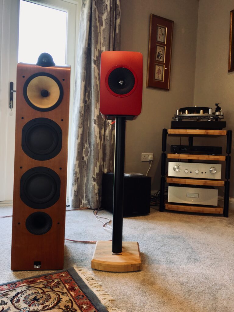
The picture below is of the kx-amplifier driving my Kef LS50s’


The kx-Amplifier uses my original sx-Amplifier chassis, but I had a top plate and nameplate made at Front Panel Express in Germany.
I listen to a wide range of music, and given the speakers I have (KEF LS50’s, B&W 703’s and a pair of Q Acoustic 320’s) I tend to use my amplifiers according to the music I listen to. I use the kx-Amp for acoustic music and light Jazz and one of my bigger commercial amps for large scale orchestral and rock/pop music. The LS50’s are not efficient – about 85dB, while the B&W 703’s fair a bit better at ~90dB. Of course if you have a pair of very efficient horn speakers (say >96 dB), the kx-Amp will quite easily deliver rock concert sound pressure levels.


Above you can see the Low/High bias switch (red) just to the left of the right hand foot

The finished amplifier weighs 10 kg’s
Pictures taken during testing and development


Please note that in the BOM has been updated on 27-06-2018: the 1000uF capacitor quantity has been increased to 6 pieces and the 220uF capacitors have been removed in line with the schematic and the PCB silkscreen.
For the 1000uF 35V capacitors, you can use RS 711-1312 (‘Jackcon’ brand) which is 10mm diameter x 20mm long or Panasonic from Mouser, their part number 667-EEU-FS1V102L also measuring 10 mm diameter and 25 mm long.
Thanks to builder Jeppe Bjoern from Denmark for highlighting this.
Andrew,
Can C4 be linked out if one can guarantee little to no DC from the source?
Thanks!
Anand,
C4 is a 10nF capacitor and is designed to ensure that at RF the bridge rectifier bypassed. If you are using the ground lifter, then you should have C4 installed. If you short C4 out, then the ground lifter (D1) is bypassed – so you should not short it out.
Andrew,
When you have time, can you also update this page with pics of the inside of your kx amplifier build. It looks marvelous from the outside!
Thanks!
Yes – I will add some internal pics – its basically the same as the sx-Amp because that’s the chassis I used but with a new top plate and added front panel badge.
Andrew,
My apologies. A bit of clarification is in order. You addressed component C4 in the PSU. My concern is C4 in the main amplifier circuit which is the immediate series capacitor that allows for AC coupling the circuit. My question is if my source has very low DC offset, can C4 be linked out?
Thanks!
Anand, you cannot remove it because it’s needed for the DC offset adjustment.
Thanks again!
Regarding matching semis, it appears that you recommend matching the BJT’s in the input stage, i.e. Q12, Q13, Q14, and Q15 as well as the driver transistors Q10 and Q11, correct?
Thanks!
Anand,
No – there is no need to match any of the transistors in the kx-amp.
Andrew,
I’m just checking in to see if you received my email 2 days ago – if not, I’ll resend or you can check your spam folder.
Cheers!
Hello Anand – sorry I’ve been very busy the last few days.
I’ll take a look tonight or tomorrow and reply – thanks fro catching those snags by the way!
Kind Regards
Andrew
Thanks to builder Anand (aka nycavsr2000 aka poseidonsvoice) for picking up discrepancies in the BOM and circuit. The changes have been made and the BOM now matches the PCB and schematic.
NOTE: R25 sets the kx-amplifier gain. If you want HIGH gain of 25x set R25 to 15 Ohms. If you want LOW gain of 17.3x (similar to the sx-Amplifier) then set R25 to 22 Ohms
Andrew,
In the past week I have sent you another revised BOM by email. Please check your spam folder if you didn’t receive the emails where I attached the revised BOM. Also please change the above date of revision since it still states 27th of June.
Thanks!
Thanks Anand – just very busy at the moment. I’ll try to take a look a little later today.
Cheers
Andrew
Andrew,
Hi again 😉
Can you tell us what the output impedance of this design is (at less than 1khz), and thus the damping factor assuming a nominal 8 ohm load? Most dynamic loudspeakers have impedance minima at less than 1khz (typically in 50-200Hz range) so this info would be useful.
I realize the output impedance of an amplifier varies with frequency.
Thanks!
Anand,
I have not measured it, but from sims and dev work I estimate it would be be <.02 Ohms at 1kHz - so a damping factor of > 400
Hello Andrew,
I was getting my parts order ready and noticed a misprint with the BOM supplier part number for R18.
Should be: MSR 273-33K-RC
Regards,
Vunce
Vunce,
I will put up an updated BOM later today (kindly pulled together by another builder Anand) – please hold off ordering until then.
Regards
Andrew
BOM updated with minor corrections etc on 01-09-2018
Thanks Andrew and Anand:-)
I’ve gone through the BOM’s several times and finally placed all parts orders for the kx and RE-psu.
Regards,
Vunce
I’ve been asked to clarify the current vs link status of J8. It is as follows
J8 OPEN = LOW Bias Current ~300mA per output pair, so 600mA in Total for the amplifier
J8 CLOSED = HIGH Bias Current ~600mA per pair, so 1.2A for each amplifier
Hello Andrew,
I have one kx channel and RE psu fired up! What is the offset adjustment procedure?
Thanks,
Vunce
Vunce,
Short the input of the channel you are adjusting. Set you meter to Volts initially, and then trim the potentiometer on the board for 0 V out. When it’s close to 0 you can switch to mV scale on the meter. Let the amp warm up for 30 minutes and then trim it up again. Once that’s done, your kx-Amp will be good to go.
Note: subsequently when you power up from cold, the initial offset will be between 30 and 70 mV, but within a minute or two will decline to 10-20 mV and after about 5 minutes will be at or below 10 mV.
Hi
I just order PCB set from ebay, since I have a 30-0-30 vac transformer, I just wonder is it possible to run this one in class AB mode with lower bias current, say 150mA
for each pairs?
Thank
Chatchai, it’s possible yes, but it probably would have been better then to build the nx-amplifier. It’s probably a good idea to get the right voltage transformer. I have not tested it at c. 45V which is the DC you will get from your transformer.
Andrew,
Thank you for sharing the offset adjustment procedure. I’ve got the first board adjusted pretty good, it fluctuates between -5mV to +5mV.
I couldn’t resist playing music through a single channel and I’m impressed so far. This amp is total quiet, no hum or other noises with my ear up to the speaker. And, you are right, no turn on/off thumps, pops or clicks.
Thanks again,
Regards,
Vunce
That’s great Vunce! The +- 5mV is fine – looks like your amp is good to go.
Andrew,
Are the any sonical benefits using separate power supplies (ripple eater) per channel? My amplifier will operate in AB mode.
br
Andrej
Andrej,
no – I do not think there is any benefit – one single power supply (ripple eater) will be ok and will give excellent sound.
Regards
Andrew
Andrew,
Thank you for perfect project. I interested for the unity gaim amplifier and I suppose that R25 needs to be increased for about 300R. Unfortunately, I have no idea regarding HF stability of the amplifier.
Please advise
Vince
Vince,
Unfortunately You cannot change R25 to 300 Ohms without affecting the amplifier performance. The best way is to attenuate the input signal to the amplifier.
Hope this helps
kx amplifier – current in output pairs is too high.
Small signal amplifier and drive stages have quiescent voltages well within spec. Output off-set settles to less than 5 mV. Rail voltage is +/- 26 volt.
In Class-AAB mode – Link J8 removed, (VR12 + VR13) measured to be 385 mV and (VR14 + VR15) measured to be 353 mV. This is almost twice what it should be. When link J8 is inserted the current rises to 1.8 amp.
Any suggestions?
Stirls50
Ian,
that is indeed on the high side. Please carefully check the following:-
R8 – must be 4.7k (check with your ohmeter)
R18 must be 33k
If these measure ok – can you lift C16 and recheck the bias current – if C16 was leaky or short, output current would be high
Likewise, if C5 was leaky you would also get this problem.
If no change, I would suspect Q7
Also make sure your emitter degeneration resistors measure 0.33 – if these were low or not the correct value, you would have the same problem – although this does seem unlikely
Let me know if this solves your problem – good luck
Hi Andrew,
Thanks for the comprehensive reply on November 25, 2018 .
R8 and R18 measure spot-on.’
C5 and C16 are ceramic and “leakage ” seems unlikely.
A friend is also building a pair of kx amplifiers I am keen to see how his amps go.
In the meantime I will order new C5 and C16 caps and new BC546B to replace Q7.
It could be a while before I can let you know what the problem is.
Cheers
Ian
Hello Ian,
Other potential problem is that it could be oscillating. Can you make sure that C10, C2 and C3 (which must be film or COG/NPO) are the correct value, and that R42 is 1.8k)
Other than that, hopefully after you have changed out the components suggested in my earlier replay, you should be good to go. You are correct, ceramics don’t usually leak, but they if they are damaged, or not at the correct voltage rating, you could see problems.
Let me know how it goes – any problems please shout.
One other thing, your compensation caps (C10, C2 and C3) should have written on them either 150pF OR 151
If they just say 150 with no pF its highly likely they are only 15pF – so check this carefully – I’ve been caught like that before.
Make sure D1 is also not short or faulty – if it is, the bias current will be much higher than specified.
hi, i am building these as mono blocks , each their own 250 va toroidy from poland, ripple eater and gigantic 2×68000 uf roederstein eyf caps ( just because i had them )
question 1: the 4 output trans 270 pf smd caps dont appear in the bom, are they necessary?
question 2: using 35 volt rails and a 3 kgs heatsink each block, is it possible to run it class a at 35 Volts?
question 3 : i put the zobel network on the main board directly because i had parts that fit , and i didnt see reason for long wires here . possible?
question4: i wanted to add 4x6800uf AFTER the ripple eater directly before the amps rail input . possible?
thanks my fruend, i think this think will outperform my omtec ca25 and maybe my revised and tweaked kenwood l07-m
Hello Rene(?)
Here are the answers to your questions:-
1. Do not fit the 270pf Caps shown on the PCB layout. These were included for a compensation scheme that was not implemented in the final design.
2. Even with 3kg heatsinks per channel, I would still not run in class A at 35V. You are seriously stressing the output devices.
3. Zobel fitted to main board – should be ok
4. 6800 after the ripple Eater – this should work ok. you can try it and see. Remeber, each PCB has 1000uF per rail so it is alrerady a lot and when combined with the ripple eater, the noise performance is very good.
Good luck with your build – any questions, let me know.
Regards
Andrew
Hallo, for the Q12, Q13, Q14, and Q15 can i use BC550C and BC560C ?
The transformer for the kx-amp has to be 2X20V
Thankyou in advance
Hello NES,
Yes, you can use BC550 and BC560.
The 2×20 VAC for the transformer is ok
About C1, C17, C18, C19 ? In the BOM i cant find anything about the smd cap. In the pcb beneath
Nestor,
These were included on the PCB but not fitted. Please leave them off.
I will add a note on the webpage about this.
Regards
Andrew
Hi Andrew,
Thanks for publishing and documenting your design so well.
Will the design benefit from thermally matching Q7, fitting it to the heatsink?
Hi Mike,
No need to match Q7 or thermally couple it to the heatsink. There’s no benefit either in terms of distortion or current stability.
Hello Andrew. I will ask you for help, I bought KX PCB set from ebay /from jim`s audio/ everything is populated to the PCB`s, the BIAS currents are set, voltage ofsets are in limits, wire harness is prepared by Your recommendations, everything go fine, except when I bond together the signal grounds from channels on Cinch inlets, imediatelly hum comes…not loud, but why? The metal chassis is connected to the Safety Ground, Ground lifter are inserted, Cinch connectors are insulated from chassis. HBR resistors has 33 ohms…When the inputs independent, the channels are dead quiet…when bonded together hum…not so loud, but present…please try to explain me where to continue the searching of solution…THX Gogola
Hello Gogola.
Am I understanding your problem is that when the input connector grounds are not bonded together the amp does not hum, but when you bond them together the amp has a hum?
Yes Andrew, You understood well..same is happening if I leave signal grounds unbonded, then I prepare connection between channels with interconnect cable….
are The input connectors located next to each other?
Hello Andrew. The distance between connectors is 24mm.
Gogola
1. You must make sure the neither of the connectors is contacting the chassis
2. It sounds like you have a cross channel loop (CCGL) inside your amp since the kx-amp has a hum breaking resistor (HBR) fitted, the CCGL must be coming from either the way the input cables are routed inside the amp OR you have a common impedance coupling problem where the amplifier 0V connects to the power supply.
Please go to the Ground Loop page on my website and download the first document. Then study pages 56 to 64 carefully to make sure you have wired and routed your cabling to avoid any problems. Make sure all power cables to the amps are twisted together including the 0V. Look carefully at how the input cables are routed inside the amp – the shortest way is not the quietest in many cases.
If you can post a photo up on the DIY audio site, it will also make debugging easier.
Andrew, thank you for quick answers…i will make everything what You described..then I will write up some words here…
Hello Andrew. I made all of Your propositions, but the amp is still hum, when I bond together channels with interconnect cable. I was created new wire harnesses, where plus, minus, 0V and Zobel return wires twisted together, ties applied each 25mm…and yesterday i was measured between signal GND versus power GND cca. 6,5mV on left channel and 10 mV on right channel…maybe this voltage diferences create the hum?
Hello Gogola,
Please can you sent a photograph of your amp. There’s a thread on DIYaudio.com dedicated to this amp where you can post it -alternately, just mail it to here.
Hello Andrew.THX for answerd, i will try to post here internal photo of my amplifier.
Gogola
About the C4. I want to use MKP and no electrolytic. Can i do it?
Nestor, you will need a value of at least 2.2 to 4.7 uF (4.7uF preferable) to ensure the LF response is adequate. The cap 22 uF cap specified is a bipolar type, so it’s very good and shows no distortion at LF like normal electrolytic types.
I have the same conserns regarding C 4. I plan to use a Wima MKS2 at 6u8, mouser part no 505-MKS2B046801MKSSD. It fits in the PCB.
Hello Ole.
You can use the Wima 6.8 uF. The -3dB bass will be at about 2.4 Hz, but this will be inaudible (versus 0.7Hz with the original 22uF)
Hi,
I have 2 Modushop Dissipante 3U 300mm 10mm BLACK front panel – 3mm aluminium covers and rear panel cabinets.
The heatsinks are temperature coefficient 0,40 C°/W but are 1.5kg. Can i use these cabinets for the ovation kx amplifier? Maybe in class ab mode?
Best regards,
Dennis
Dennis, yes this will be fine for class AAB mode. You may be able to get way with full class A. The main thing is to keep the max temp to not more than 55 C
Hello Bonsai,
That is great to read. What is the best Voltage for the transformers? Should i go for the 35v only class aab or the lower one?
Greetings and thanks for your time
Dennis with your heatsink rating of 0.4 deg C (I assume you have 2 heatsinks) I would go for the full class A – so the lower voltage as specified in the arrticle.
Here is the temperature calculation
Total supply voltage is 2 x 28V = 56 V
Total current draw for class A 1.2A
Total power dissipation (per channel) = 1.2 * 56 = 67 Watts [THIS IS PER AMPLIFIER CHANNEL – TOTAL AMPLIFIER DISSIPATION IS THEREFORE 134 WATTS]
Heatsink thermal 0.4 deg C/watt
total heatsink temp rise is 67 watts * 0.4 = 27 deg C ABOVE Ambient
Assume ambient is 27 C
So heatsink temperature is 27 C + 27 C = 54 C PER CHANNEL
If your amp runs too hot for the heatsinks, its very easy to dial the quiescent current down a bit.
Regards
Andrew
Hello
Thanks for this very nice design
I get a bias current hotter than specified: with J8 open V(R14+R15) or V(R12+R13) = 280mV instead of 200mv. Tests with a lab power supply in the standard KX power supply (to have the Zobel connected)
The lab power supply show 0,95A total for the whole board (slow rising to 1,0A with temp)
Set for +-27V on the rails
All other values matched specifications
R18 marks on resistor show 33k. When I tested unpowered on board, measurement is 29k.
I have checked D1 and Q7: seems to work properly
Sames values ( at 2%) on the other board
No oscillations but I have just checked with a Picoscope (limited bandwith 15 MHz)
On a dummy load of 8ohms
I can send you some photos of the square waves at 1khz and 20khz (seems OK)
And of the amplifier
With Tiger transformer and standard Kx power supply I get about 29V on rails
Regards
Philippe
Hello Philippe,
Thanks for your kind words. You can expect a variation in the standing currents of around 20%. In itself this should not be a problem. If you are producing square waves accurately with a 15 MHz scope BW I would think the amp is working ok.
However, let me take a look on Monday and come back to you then – I am with family this weekend.
Kind regards
Andrew
Hello Philippe,
I’ve had another look at your problem. If all the devices are ok as you say, there are a few other things to check:-
R8 – if that was high it would also cause the standing current to be high
0.33 Ohm resistors – these are often +-5% or +-10% – this would also cause Iq to be higher than expected
C16 – if that was leaking this would also cause Iq to be high. Since this is an issue on both boards, it seems this is unlikely though but I would check it nevertheless.
Please check to make sure the voltage drops across R11 and R10 are c. 450 mV +-50 mV. If this was high, it would also cause Iq to be high.
If these all measure ok, I would assume the amp is ok – you just have one on the very upper limit of Iq.
Regards
Andrew
Hi Andrew
Thanks for your answer.
I will check all the points at the end of the week. For R10 and R11, it was on the list of checks (450+-50mv) and I don’t remember for a “out of specs” value. But I will check again of course
For R8, before you answer, I was thinking to solder a parallel resistor of 27k (so that the equivalent resistance decrease to about 4k)
According Pspice calculations, It would do the trick and it ‘s easier to do that than to desolder and replace R18 with a higher value
I also made new measurements (square waves 1k, 10k, 50k) with a 50mhz scope and I would like to have your opinion.
Can I send you the pics ?
About noise: first I got a very little buzz (not hum) when both inputs connected (I can only hear that with my head close to the loudspeaker ). Amp was dead silent with inputs shorted or disconnected.
I have discovered that the way the power cables to the the boards are dressed is very important: no noise at all after a minor change. I’m very happy
I will try to post post photos before and after (on DIYaudio?). Perhaps, it will be useful for others builders
Regards
Philippe
Philippe
Philippe,
Last name removed from post.
Please feel free to post your pics up on DIY Audio.
R8 solution is ok. I will have to do some more simulations to see what he worst case spread is for the amp. I tried to avoid having an adjustment potentiometer in this design. I may have to open the Iq spec range up a bit based on your findings – but I need to check it first.
Cable dressing is very important. Please see the ‘Ground Loop’ presentation on this website for further information. One test you can do for cross channel ground loop is to connect a cable from the left channel to the right channel and then see it you get any hum. This is often a problem in DIY amps – cable dressing and hum breaking resistor is the cure ((the kx-Amp has a hum breaking resistor so this part of the solution is already in place).
regards
Andrew
Andrew,
Keen to try and build your kx.
How would your Kx amp fare with electrostatics (Quad & Martin Logan) as these are reactive? I normally don’t listen at loud volumes (60-75 db).
Second question, can one add another output transistor pair together with larger heatsinks to reduce the thermal stress on the devices. I like it as cool as possible. The aim is not to get more power. I can design my own pcb’s if it all makes sense.
Kind regards
Miklos, can you tell me which ESL’s you are using so I can check the impedance and phase?
In class A mode, the recommended supply voltage for the kx-Amp is +-28V so at this point the output devices still have a very large SOA.
Re the temperature, my one runs at about 55 C in the summer and to be honest the heatsinks could be a bit bigger. I switch mine between class A and class AAB which halves the standing dissipation. I would not get too hung up on temperature – aim for 50C by using large heatsinks and your amp will be reliable. I used my sx-Amp for nearly 8 years without problems before disassembling it to use the chassis for the kx-Amp and the heatsinks ran at 55 C ( it was left on sometimes for weeks at a time).
Regards
Andrew
Hi Andrew
Thank you for your reply. Presently I am using the ML Summits, but I have used the Quad esl 63 quite extensively and with certain music I prefer the 63’s. I am now nearing retirement and looking for a nice project to put my hands on and this seems to fit nicely.
Kind regards
Miklos
Hi, I took a look at the specs – the only one I could with an impedance trace was the ‘Montis’ review in Stereophile. On the ML website, they specify the Summit at 92dB efficiency which is not too bad. The impedance curve is only very low (c. 2 Ohms on the Montis) at HF where you have little music energy and the protection of the kx-Amp output L.
So, you could go for the full class A version at +-28V rails, or the class AAB version on +-35V rails which will give you about 50 Watts into 8 Ohms and nearly double that at 4 Ohms. In class AAB, you will still have 6 or 7 watts in class A with this approach.
If you go class A, make sure to use large heatsinks – it really pays dividends for reliability in the long run.
I leave it up to you to decide, but if you have any problems, just let me know.
Good luck with the build and retirement! Enjoy!
Hi Andrew
I am hobby building own mostly VFA designs with Mosfets.. The time has come to try CFA with BJT’s so I have bought some PCB’s of the KX. How do you think DC servos would work in a CFA design? BTW can you give some details on how thermal stability is achieved in the KX design. Does the bias spreader track the output stage?
Claus from Denmark
Hello Claus, thanks for your questions.
1. DC Servos. Yes, you can use a DC servo with a CFA. My Model 1721 240W per channel CFA commercial amp uses a servo. I did not use servo’s in any of my DIY designs because it adds some complexity and once the DC offset is dialled out, they are very stable (typically +-5mV after warming up).
2. On the kx amp, the output stage standing current is electrically regulated with a feedback signal from across the 0.33 Ohm output degeneration resistors. This is not the same as a class B amplifier where the output stage current is not controlled by an electrical feedback path, but simply with a thermal feedback path i.e. the bias controller senses the heatsink temperature in a class B amplifier. The kx-Amplifier standing current is quite stable over temperature and can never have a thermal run away problem. If the output load current demand exceeds the class A capability, the OPS moves to class AB operation, returning to class A (AAB) when the load conditions allow it.
Regards
Andrew
Hi Andrew
Thanks for your reply. I am looking forward to build and hear your KX design.
Would the KX thermal feedback system work for Class AB? The voltage across the degeneration resistors are in this case 60-100mV I would guess. Or would you prefer a normal thermal coupled bias spreader for larger Class AB designs?
BR
Claus
Hi, for class AB I think the common method using a thermally coupled only bias spreader to control the OPS standing current is the way forward. Since the sense voltages across the OPS degeneration resistors are small (30-80mV in typical designs), you have to provide some form of amplification, or, a stable thermally adjusted offset which complicates things unnecessarily in my view. If you try to use a straight bias spreader on a class A amp, it gets quite difficult to get it stable, and you always run the risk of thermal runaway – so this necessitates very thorough testing over the full operating envelope of the amplifier.
So, in summary, for class A it makes much more sense to directly regulate the output stage current and for class AB the standard bias spreader seems the best way forward.
Hi Andrew,
Recieved the KX PCB’s recently. I wonder if the four 270pF SMD on the solderside of the PCB’s should be mounted. I guess they are there to stop parasitic oscillation. They are not on the schematic. Should I mount them or first test under different loads and see if they are necessary?
BR
Claus
Claus,
You are correct – they should not be mounted.
Also please download the latest build doc from the kx-amplifier page – it has the mods needed to prevent HF parasitic oscillation in the OPS.
Any questions, please let me know. Good luck with your build!
Hi Andrew
I have now a lab version of the KX amplifier running in my home lab. I have the PCB’s that does not contain the latest modifications but I have implemented 1K resistors at the beta helpers and 4,7ohm in the hum breaker. Furthermore I have chanced R1 to 33K because standing current was app 1.6 amps which is high at 28V power rails. Standing current is now app 1,4 amps.
I use KSC1854 and 2sc992 in the input and TIS stage. I made the mistake of using KSC1845 in the bias spreader. This does not work because saturation voltage in the KSC1854 is over 2 V at 10mA. Instead I use BC550C now. Now everything works fine.
I am impressed with the performance. THD in 8ohm at 15W is app.10ppm in high bias mode Low bias mode with app.800mA standing current is app 20ppm.
Other measurements I did: Noise (4-5nVsqrHz) risetime 650 nsec. More days of fun is waiting.
Did you measure damping factor? I measures about 60 in 8 ohm’s 1KHz?
BTW I have made I protect circuit with the LM339 circuit from Bob Cordells book and your Solid state relay combined. I don’t like connecting loadspeakers directly to an output stage without protection. The combo workes fine, and it does not change damping factor.
Main learnings for others is the transistor choice in the bias spreader.
Claus, fantastic that you got a good result with your amp – that’s good news.
For the spreader, its not actually working as a spreader in the kx-Amp, but more as a direct OPS current regulator. In a normal class AB or class B amp, the primary feedback mechanism for the bias spreader is temperature. As it increases, the spreader voltage as measured across the collector<>emitter decreases because the Vbe of the spreader is decreasing because the threshold voltage goes down with increasing temperature (by approx. -2.2mV/C).
On the kx-Amp, The voltage drop across the output degeneration resistors is measured directly, so its a voltage regulation scheme. there is also temperature compensation, but it is secondary to the direct regulation. If you look at the X-Altra HPA-1 headphone amp, there is the formula for calculating the current in there.
Anyway, I am pleased your amp works well – let us know how you like the sound after you have been listening for a few days.
Hi Andrew
I used the wrong word. I understand that the Bias control works as a voltage regulator. The issue was that the transistor I used went into saturation at 2-3V (C-E). Changing it to a BC550 solved it and enabled the regulator to work.
I have a question related to RCA mounting on the chassis. Should they be close together with interconnected ground or on each side of the chassis as one might deduct from the drawing in the kx documentation?
BR
Claus
Ahh – ok – my misunderstanding.
re the input RCA connectors, its always better to put them next to each other and bond the signal grounds together. Then run both cables together inside the amp, drop off to the first module and run the other cable around the edge of the amp all the way around to the other module. This keeps the total loop area between the two channels at a minimum.
I strongly recommend you use the ‘headphone ‘scope’ trick when you route your cables to find the lowest noise position for the wiring. If you look at the ‘Ground Loops’ presentation here
http://hifisonix.com/wp-content/uploads/2019/02/Ground-Loops.pdf
Pages 61-66 show you how to do it.
Hi Andrew,
The design is almost ready for listening test. Just need some parts from Mouser to finish.
One question. How does one design balanced input on a CFA design? I have in my own design used THAT1200 with a 1K-1K ohm voltage divider on the out to keep noise down. Is this the best way on a CFA amplifier?
BR
Claus
Hi Claus,
The THAT 1200 type devices should work well – I use them on my commercial gear and have never had any problems.
Rgds
Andrew
Hi Andrew,
I have listened to the KX amplifier now. The impression is a big soundstage with a totally silent background. Impressive sound. What strikes me the most is the soundstage. Bass is also impressive with lots of grip and precision. The KX will be in my living room a lot!
One thing I learned! Never connect the ground (speaker GND) with the input GND. When I short the hum breaking resistor, the amplifier goes into oscillation. (app 1MHz). Is there a reason for this? When I use my QA401 in balanced mode, the issue is gone,
regards
Claus
Clause, the offset adjustment is done on the input of the kx-Amp. You therefore must not short out the hum breaking resistor as it will cause problems.
If you are using a balanced input adapter on you amps, then you should not connect the input grounds – this will cause problems.
Hope this helps.
Hi Andrew
Sorry to bother you again.
It seems that I have a problem with oscillation when I connect the two input grounds together. Both amplifier modules oscillates at app. 250KHz. I have checked cables, and I think I have connected everything OK. When I disconnect the grounds, oscillation stops. Since the frequency is low, I suspect that the amplifiers oscillates within the feedback loop, and the problem is not HF related. I have used 15 ohm resistors for hum breakers, because DC offset was tough with 4,7 ohm. Do you have any ideas?
BR/Claus
Claus,
Sorry to hear you have a problem. R9 is the hum breaking resistor and is 33 ohms.
Please disconnect the input grounds. Short both inputs. Adjust the offset pot for 0 mV at the output of each amplifier (allow the amplifiers to warm up for about 10-20 minutes before doing the adjustment).
After this, reconnect the input grounds.
There should not be any loop instability – the gain and phase margins on the kx-Amp are very generous >15 dB and c. 80 degrees.
Let me know how it progresses.
Hi Andrew,
Thanks. I suspected that this was the issue. I think I will use a balanced line driver to drive the input. Since there is DC blocking capacitor, DC offset from the eg. THAT IC wont be a problem.
Thanks
Claus
Great – let me know after a few days of burn-in how you like the sound of your kx-Amps.
I am using mine with B&W 703’s and occasionally with my KEF LS50’s – mainly big band Jazz, Ella Fitzgerald and a lot of classical music on vinyl. I can switch between class AAB and class A and definetrly prefer the class A sound after about 30 minutes warm up.
Hi Andrew,
Followed your instructions. 33 ohm hum breaker, warm up, and offset adjustment to close to 0 mV. Individually the amplifiers perform very well. If I connect the two input grounds on the RCA jacks the amplifiers oscillates and draw heavy current from the safety transformer.
The only thing I have done to the PCB’s are the decoupling capacitors and 1K resistors on the beta helper transistors. Otherwise it should be OK. Obviously there is a difference if I have a problem and you don’t?
BR/Claus
Claus,
If you are using balanced inputs, why are you joining the signal grounds?
What happens if the input grounds are not joined, but you amp is connected to a source (I assume a preamp)?
Hi Andrew
This morning I tried to connect a preamp (Cambridge Audio 840E) RCA outputs to the two input boards Right to Right and Left to Left. No Ground wiring interconnect. Same story. Both amplifier oscillates when I increase voltage to about 170VAC on my vario transformer. (230V also oscillates). The rail voltage to the amp stages is +/-26,5V and current draw in class A mode is 400mV +/- 20mV=1,2 amps.
If I remove one cable, oscillation stops!
Tried to measure rail voltage with a 300MHz scope. No noise or odd things,
Also tried to remove everything but Pos, GND,Neg rail wires. Also zobel wire to the ripple eater. No change.
Next step will be to check every component and PCB’s. I guess the KX amp should be able to work in stereo mode. If there is 100 of them build it is probably a fault in my setup???
BR/Claus
Claus, can you send me a picture? Are your HBR (R9) at 33 ohms? Also can you confirm your load (speaker or resistor).
Just so it’s clear for me:
1. If you join the two grounds at the input, it oscillates but if you do not join the two grounds it’s ok?
Or
2. As soon as you connect the 2 Nd channel, it oscillates but not with just one channel connected (with or without the grounds joined at the input)
Thanks
Clause, I do not understand this:-
“No Ground wiring interconnect. “
Do you mean you did not join the signal grounds at the kx-Amp input?
Hi Andrew,
Understand! Perhaps my explanations are not that good.
The PCB’s are build as described in the 2018 version schematic. The only difference is that I have used KSC1845 and KSA992 for the input stage and beta helpers. Further I have changed beta helper resistors to 1K and have added 1uF capacitors across 1000uF/35V capacitors. The changes are described in the first part og the documentation you have made.
Hum resistors are 33 ohm.
My reporting has been a bit confusing for you because I have tried a lot of things. Sorry for that.
The issue is that when input ground (in front of 33 ohm resistors) is connected between the amplifiers, both amplifiers oscillate and draw heavy current from the PSU. It does not matter if connection is made on the RCA connectors, or in a preamp. I have measured and checked PSU, cables, connections, but obviously miss something. I have measured the voltage between the two input grounds. It is less that 1mV. I suspected that there could be some current flow in the input ground?
If you can share an email, or other. I can send you pictures of the setup?
BR
Claus
Claus, can you email me at bonsai(at)hifisonix.com
Cheers
Andrew
Hi Andrew
What is the best way to connect the xlr output to kx
Hello Gregor, I use a XLR to RCA adapter cable – that’s the quickest easiest way.
Hi Andrew,
I’m thinking about building the KX2 amplifier as it seems to exactly suit my needs. The ability to switch the amp to pure class A for serious listening sessions and back to AB for everyday needs is great. Furthermore the level of detail in the instructions is impressive.
Right now my audiopath is fully balanced from DAC via preamp to my current power amps. Is it possible to modify the input stage and mount XLR inputs?
Kind regards and keep up the great work,
Ed
Hello Ed,
thanks for your comments! With the kx2 you can switch from class A to class AAB and then class AB. Unfortunately it is not possible to modify the input stage to accept balanced inputs because the kx2 is a CFA – so one of the inputs is low impedance (about 33 Ohms). That said, few voltage feedback amps are structured to directly accept balanced inputs unless they have JFET input stages or a buffer which then allows reasonably high input impedances on both input legs to be arranged.
One option would be to use a balanced to single ended converter chip like the THAT1206 but I don’t have a board to do that at present. The other alternative, which I have used successfully is a balanced to unbalanced RCA cable which you can get on Amazon. I ran my sx-Amp like this for a few years.
Hope this helps
Rgds
Andrew