
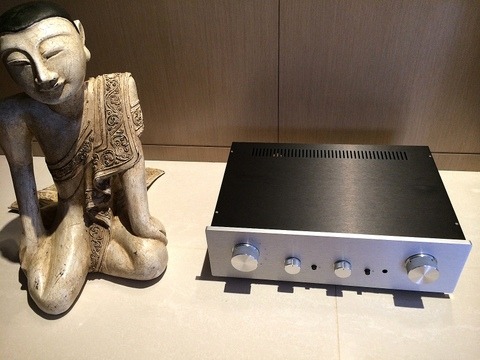
I designed and built this preamplifier while living in Taiwan a few years ago. The Symphony preamp features Baxandall tone controls, up to 7 inputs, a class A 2 W headphone amplifier and a Goldpoint 24 position attenuator. The write-up describes the design process and choices in some detail and my listening impressions:
Part 1 – Ovation Symphony Line Preamplifier V1.0
Part 2 – Ovation Symphony Line Preamplifier V1.0
Specifications_Line and Output Only
Introduction
I have designed and built two preamplifiers over the past few years, this being the third. The first of my recent efforts – after a 25 year layoff – was the X-Altra Mini One, which featured an ultra-simple signal chain based on an LM4562 op-amp. The second was the experimental SCA-1 which was an all-out top of the range IC based design using a TI PGA2320 chip configured in balanced mode, along with LM4562, LME49600 buffers and a headphone amplifier. This design had no tone controls of any sort, but featured a remote control and a 5” GUI TFT display, all controlled by an NXP LPC1768 ARM based mbed controller. I have not got around to housing this design yet – I guess the expense of a large custom case has put me off for the time being. This brings me to the current project, the Ovation ‘Symphony One’. I designed and built a few pre-amps in my early 20’s that featured Baxandall tone controls and headphone outputs, and after reading about Douglas Self’s latest design in Elektor, I was inspired to try my hand again at a full function preamp, incorporating decent (i.e. Baxandall) tone controls, a class A headphone amplifier and an optional MC/MM input board, which would be designed at a later stage. With no pretensions to convenience, this design does not cater for remote control, and has no fancy 5” TFT display like the SCA-1. However, this preamp features the following:-
- The design uses low noise opamps in the main signal path, to achieve outstanding noise performance
- All the op-amps are buffered with discrete class A output stages and their outputs are also bootstrapped at around 600uA into class A mode. The buffers are inside the opamp feedback loop
- All class A operation means the supply lines carry only the fundamental of the output signal and low order harmonics – so no wide band harmonics as is the case with class AB operation, reducing noise and any impact on distortion performance due to magnetic coupling of these higher order components into sensitive circuit nodes; further, with this technique, HF excitation currents are kept off the supply rails, minimizing potential ringing on the supply lines (see Kendall Castor-Perry’s articles on power supply decoupling for example)
- Heavy filtering of the PSU ADJ pin means the wide band noise is about 20 µV, while the additional 22 Ω and 100 µF supply filter on each opamp supply pin reduces HF noise further, and provides tight, localized decoupling for each active amplifier/buffer stage.
- The design uses ‘back terminated’ input signal select switching to deliver very high input ‘offness’
- Strict attention to physically separating the left and right channels keeps channel separation high
- Distortion at 1 V RMS output into 10 kΩ is in the region of 1ppm at 20 kHz, and at 8 V RMS out into 600 Ω better than 5 ppm, again at 20 kHz
- A Baxandall tone control (which can be completely bypassed) offers +-10 dB of boost and attenuation at 100 Hz and 10 kHz with distortion of < 15 ppm at 20 kHz and 10 V peak out
- This preamp features a very high performance headphone output that will drive 32 Ω to >3 V pk-pk and still remain in class A operation at less than 10 ppm distortion at 20 kHz
- 7 input sources and a switchable buffered tape loop
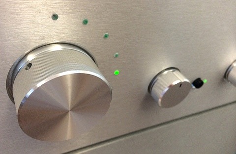
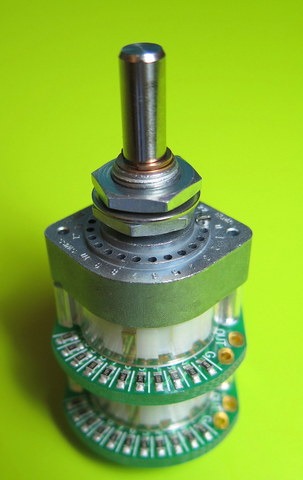
- The volume control is a front panel mount Goldpoint Mini-V 5k log taper unit for the ultimate in transparency and tactile feel

Design Approach: Some General Thoughts
My 2008 X-Altra Mini One preamp is a minimalist design that eschews tone controls and really focuses on doing as little as possible with the source signal, other than providing source selection, volume control and some gain and buffering in order to match the typical 1V required to drive a modern power amp. Input source selection is based on small signal relays (Panasonic AGN series), which, along with a carefully designed power supply and layout, allows this design to achieve about 5 ppm at 20 kHz distortion at 1V RMS into 600 Ω, and <70 ppm at 6.5V RMS into 600 Ω, again at 20 kHz. If applied correctly (and that’s easy to do if you just follow basic, simple layout and circuit design practice) the LME4562 is a wonderful sounding chip. Sloppy layout, bad decoupling and other avoidable design missteps can lead to problems – you are dealing with a device with an OLG of 140dB at LF and a ~55 MHz GBW. In the write up, I comment on the very good sound – open mid-range and top end along with first class imaging. Direct coupling means bass performance is not compromised, and there are no opportunities for electrolytic sonic intrusion, inasmuch as this is a problem with a carefully chosen component.
A year or two later, this was followed up with the Ovation SCA-1. Again, no tone controls, but the volume control and main gain element featured a TI PGA2320 configured in balanced mode, with buffering before and after using LM4562’s and LME4900 unity gain buffers. The PGA2320 has taken quite heavy criticism in some quarters, with claims that they are sub optimal in sonic terms or noisy and so on, but my practical experience is different. You need to feed them from a low source impedance to get the best noise and distortion performance (so something well below 1 k Ω) and the outputs do need to be buffered – although I would say this applies to any op-amp based design that has ‘high end’ pretensions. In the SCA-1, the balanced input signal after the relay selection stage is buffered by a dual LM4562 opamp, which in turn drives each channel of the PGA2320 in balanced mode. The output of the PGA2320 then feeds into an inverting stage and an LM49600 high current buffer, which is inside the opamp’s feedback loop. This configuration will drive a 20 V pk-pk balanced signal into 200 Ω with less than 3 ppm distortion at 20 kHz. At 1V RMS out into 600 Ω, the distortion is a few hundred ppb. A servo keeps output offsets to less than 50 µV. Most of my assessment of the SCA-1 (both subjective and in comparison with the X-Altra Mini, Marantz and various iPods and CD players) has been done with an assortment of headphones including Sennheiser, Audio Technica ATH-900, some Sony IE’s and a very high end Stax tube based system along with some evaluation sessions on the Ovation 250. The design features a very open top end, great bass, imaging and low noise. As further independent evidence to the performance potential of the PGA2320, a 2008 review (and there are more recent iterations of the C-03 that still retain the PGA2320 as the main gain control element) of the top of the line C-03 Esoteric line preamp which uses this chip as the primary gain element and retails at over $10k, gave it top marks for sonics and overall audio performance. In fact, the reviewer claimed it was one of the very best line preamps he had ever heard. And, this was not the only review to similarly rate this Esoteric preamplifier in the top echelon – so did 6 Moons amongst others, and Stereophile also had very positive comments after hearing a system built around one. When thinking about high end audio, one’s component and semiconductor device prejudices are best set aside I have found – whether you believe equipment reviewers or not.
Both of my recent designs (X-Altra Mini and the SCA-1) tell the brutal truth, and especially so with respect to recording quality. But, there is no doubt that the two biggest – by an order of magnitude or more – contributors to sound perception are the recording itself, and the speaker + room interaction. If you have a reasonably large record or CD collection, this can leave you with recordings that lack the right kind of balance given your specific room/speaker setup. Some commentators believe a good speaker will sound good in any environment, and if you think you have a sound problem, then your system is not up to standard. I take the view that in most cases the system is capable of very good performance and it’s the room that’s not always up to the task. I have about 50 CD’s out of 500 that are almost perfect for my listening environment: the bass and treble are well balanced, good imaging, and the overall sound well integrated and pleasing to the ear. This leaves a lot of recordings in my listening environment which need some response balancing and the requirement for a decent tone control, which will be discussed in some detail a little later.

Douglas Self’s two major DIY preamp designs have featured another of Peter Baxandall’s innovations, his Active Volume Control. This approach varies the feedback factor in an active gain stage to achieve a volume control range in the order of 100:1, or about 40dB and it achieves a log like response using standard linear pots which are always easier to get hold of, especially in the 1 k to 20 k range. There are clear advantages to this design, and the fact that the gain need only be as much as is required for ones desired listening level means that it always provides the best signal to noise ratio for a given output level. Some concerns with this configuration are that you have to hang a potentiometer off the sensitive summing node in an opamp feedback network, but the same criticism of course can be levelled at Baxandall’s tone control, or any inverting, current summing circuit for that matter.
Careful layout, screening and the use of quality potentiometers will get a design the rest of the way to decent performance. However, non- summing junction topologies do not suffer from these issues, and any noise appearing between the feedback junction and the amplifier inverting input is amplified by the closed loop gain only, which in a high performance opamp based design, is theoretically a difference of over 100 dB compared to inverting variants. Of course, the issue I raise here applies equally to the Baxandall tone control, where the summing junction is fed from a resistor (from the bass side) and a capacitor (from the treble side). Again, careful layout is required to mitigate any problems. Let me stress, we are talking about noise pick up between the feedback network upper and lower resistors junction and the inverting input of the amplifier element, and not about the inherent noise performance of the inverting or non-inverting configuration.
On the Baxandall active gain stage, the summing junction input impedance at high gain settings can be very low, placing a heavy load on the opamp such that it would be exiting its class A region in the presence of very small output signal levels – just the opposite of what we would intuitively expect. I did some simulations, and the drive current required using a 1 k pot feedback element with maximum gain selected is indeed high at 10 mA. A good opamp (like an LM4562) can easily drive this type of load at 1-2V with single digit ppm distortion levels at 20 kHz; Thus, with say a 10mV output signal in this scenario you could expect 100 ppm distortion. However, I would not consider this a design flaw – maybe at worst an idiosyncrasy of the circuit. Besides, if it is of concern, it is a simple matter to place a class A discrete buffer following the opamp and ensure it is enclosed in the overall feedback loop. Self paralleled opamps in his design to reduce noise and this also solved the drive issue, so his Elektor preamp achieves very low distortion as a result.
A more conventional approach might feed the input signal straight into a potentiometer (sometimes after buffering), placing a gain of circa 5x after this to provide signal level matching to the power amp, which typically would require 1V to drive it to full output power. In this scenario, we are placing a gain stage after the attenuation element, so the amplifier will always be contributing a fixed amount of output noise (ignoring for a minute the current noise contribution which will vary with potentiometer setting). So, at high attenuation factors (so low listening levels), the signal to noise ratio can be severely degraded if the gain element is not carefully chosen. The best signal to noise performance for this type of design is when the volume control pot is set to maximum, so the amplifier noise is masked by the high output signal levels; of course, the source will also probably have a low output Z, so the noise with no signal in is likely to be low in this situation in any event. Most pre-amplifiers use this approach, and with modern gain elements and volume potentiometers typically at about 10 k Ω, the overall subjective performance remains very good. A prime concern usually cited by designers who select this signal chain configuration is to do with overload capability. You can feed in a 2V CD signal into this type of preamp on one of the non-CD inputs (CD inputs are usually attenuated by 20 dB to bring them into line with tuner and recorder output levels which are 200 mV), and by simply adjusting the volume control can prevent any overload. This is how the X-Altra Mini One is configured, and how the attenuation in the PGA2320 is also accomplished (the PGA2320 also offers up to 31 dB of gain which is done by adjusting the feedback factor of the internal opamp gain stage above attenuator settings of +0dB) – this gives an improvement in S/N ratio at low attenuation settings when the opamp is running at unity gain. In my SCA-1 design, the maximum gain as set to 16 dB and the noise levels were extremely low.
However, the third alternative is to amplify the signal first and then attenuate. Further, you can provide a higher input impedance load to the source components, like 47 k or 100 k rather than the 10 k of the input volume control potentiometer, which can be useful if for example you are driving the preamp from a tube based cathode follower where the output impedance may be many k Ω. The output of the amplifier stage can be buffered, biased into class A and thus drive a low value volume control pot, for example 1 or 2 k, which brings with it improvements in noise performance in the follow-on buffer stage. This carries the overload risk, but gets around the noise degradation. But, the overload risk is greatly exaggerated in my view with this type of design. Most digital signal source outputs today (2014) are 2 V, while legacy sources such as tape recorders, analog tuners and so forth, around 200mV. Almost any power amp available on the market will be driven to full output with a single ended 1 V input signal, with some requiring 1.5 V.
This leaves us with two options: attenuate the digital sources by c. 6dB to get the 1V full scale output and amplify the legacy sources by ~14 dB to get 1 V out from 150 mV to 200 mV input full scale. For the Ovation Symphony, I chose the latter course of action, since I will be providing an MM and MC input facility, and possibly a tuner in the future. Further, if you attenuate by 6 dB on the digital source inputs like CD players or music servers and you assume quite reasonable 10k input impedance is required for the pad, this leaves you with a 2.5k source resistance (parallel 5 k resistors with the pot set at the electrical mid-point). You could buffer the digital source first and then drive a low impedance divider, say 2 k for an overall source impedance of 500 Ω, but there is added complexity and the distortion and sonic contribution of an opamp is not zero, whereas good resistors can easily achieve <100 ppb and they don’t require a power supply, decoupling and so on. However, if you go the 20 dB padding route to level all the signal sources to the 150mV ~ 200mV range before boosting them back up by 16 dB to the 1 V required for the power amplifier, then overload can be avoided and you end up with the best of both worlds: Noise is attenuated along with the input signal but unlike the Baxandall active gain stage, there are no potentiometers – with the risk of picking up noise – hanging off a sensitive, 16 dB gain, summing junction. A 10 k 20 dB pad offers a source resistance of ~900 Ω to the 1st stage buffer/amplifier which can get you to the benchmark >110dB SNR ref 1 V out provided the gain device has decent low noise performance.
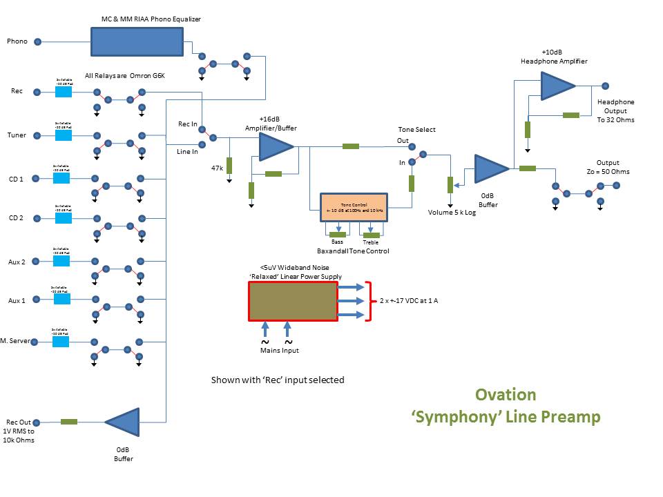
Fig 1 – Ovation Symphony Block Diagram
Ovation Symphony System Level Block diagram (Fig. 1).All of the inputs have jumper selectable -20 dB pads, feeding a low noise 14.4dB gain stage which then drives a 5 k Goldpoint log volume potentiometer. With a nominal 200 mV input signal and the opamp stages running off +-15 V, assuming 12 V pk-pk undistorted output swing, the overload is 20 dB – plenty when the amplifier can be driven to full power at 1V input level. The 20 dB pads are built around a 9 k+1 k divider, so the worst case source impedance seen by the gain stage is about 1000 Ω when selected including the source driving impedance, and when fed directly from a source, much lower than this – you can safely assume on modern equipment 50-100 Ω. There is a small noise penalty to pay for this type of divider arrangement, but in my assessment it does not detract from the overall subjective sound of this pre-amplifier. In the worst case mid resistance setting of the volume control (2.5 k), the parallel combination of the two halves of the potentiometer is ~1.25 k. Since there is no amplification taking place after the potentiometer, only buffering, the noise contribution is very small, and referred to the input, the buffer stage noise contribution is divided by the gain of the preceding stages. Of course, if the tone control is switched in, the noise contribution of the tone control has to be factored in. But, again, because of the way the signal chain is configured, and the use of 5k potentiometers in the tone control section, even with full treble boost, this preamplifier is still incredibly quiet. Further, since for most listening, the volume control will be set between the 9 o’clock and 1 o’clock positions, noise generated by the preceding stages will be attenuated: you get all the benefits of an active volume control with, dare I say, none of the drawbacks.
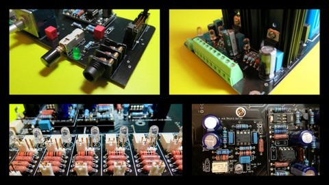
Small signal relays.I’ve read a lot of commentary on the web about relays in high-end audio applications. There seems to be a fear that after a while they will fail, or the contacts will become corroded or damaged, affecting the signal seriously. Small signal relays like the ones used here are incredibly reliable – after 10 million operations with a load of 10uA, the contact resistance is specified within 10 mΩs of the original 30~65 mΩs of the sample set at the start of the test – the device is specified at 100mΩs contact resistance. The Omron G6K is rated for 100 000 switching operations at full load, and 50 million mechanical operations – i.e. no or very low contact load. Some relays specify potential contact problems if continuously powered up due to outgassing of the plastics and insulation used in the relay. My X-Altra Mini One is never powered down (on 24/7 for months at a time) – I’ve had no problems on the AGN type relays. Another specification that people have concerns with is the minimum rated contact current – a typical spec being 10 µV~10 mV at 10 µA load current where there is a fear or concern that you cannot switch lower levels without affecting the sound. These specs are normally limited by the test gear – not the relay contact performance. Measuring and testing 10 µV~10mV/10 µA contact performance in is no easy task – thermoelectric issues between the contacts under test and the measurement gear for one pose a significant challenge – and trying to do this in a high speed automated test set-up would be expensive. Switches have exactly the same issues and for the most part they are not even sealed. Sealed relays keep atmospheric contaminants away from contacts, and at low signal switching levels, the gold clad contacts stay clean providing consistent contact resistance performance. Let’s also not forget the high frequency performance of small signal relays – they are generally also quite capable of switching RF up to 20 or 30 MHz with minimal loss and therefore qualify as very wide bandwidth devices. A further important benefit of relays is that you can locate the switching close to the signal – long PCB tracks or wires with potential cross talk problems are avoided, as is the case with switches.
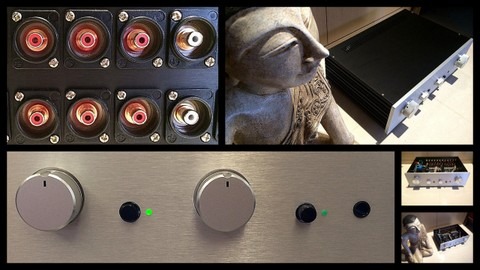
For the input source select relays, I used Omron G6K2P series devices. A good reason for their great performance of course has to do with the small physical size, silver with gold clad contacts, and importantly, the fact that they are sealed – so no issues with the ingress of atmospheric contaminants. Another great relay for this type of application is the Panasonic AGN – this is physically smaller, but also features a fully sealed, silver with gold clad contact construction. Neither of these relays is cheap, but they offer a long life and consistent contact performance. In this design, the relays are configured in a ‘back terminated’ arrangement so that the wipers are grounded when an input is not selected, resulting in very high ‘offness’. In conventional arrangements, if you turn the volume fully up with a source playing on a non-selected input, you are likely to just be able to hear bleed through, even on a good layout due to capacitive coupling across and around the contacts – and the problem gets worse as the receiving input impedance gets higher. With the arrangement shown here, there is zero signal bleed through – the technique is very robust in this regard. Of course, for balanced inputs, you will need two relays, rather than the one shown here, so it quickly becomes an expensive proposition. However, in a top end design, which is what I am targeting here, this is not an issue.
The tone control is located on a separate PCB, which also has the headphone socket, mute and tape loop switches. The tone defeat switch allows the tone control to be completely bypassed with the signal routed around the tone block. Note that no switches are used in any of the signal routing duties, including the tone control bypass – this is all done with the Omron relays – the front panel switch simply applies power to the tone bypass relay coil, located on the main board.
The output from the tone select relay feeds the Goldpoint 24 position log law attenuator, and from there it is routed to the output buffer and the headphone amplifier. The output buffer, like the input gain stage and tone control, is also an all class A stage capable of driving 200 Ωs to 10V pk in class A. For the headphone amplifier, I had the choice of going for an LM4990 buffer in an opamp feedback loop as I did on the SCA-1, but this is class AB, and my stated goal was ‘all class A’. The end result is a 2W class A design that features under 10ppm distortion at 3 V output into 32 Ωs, while in class AB it can deliver ~4 W into 32 Ωs.
Leave a Reply