Your basket is currently empty!

Using the QuantAsylum QA401 for accurate Audio Measurements
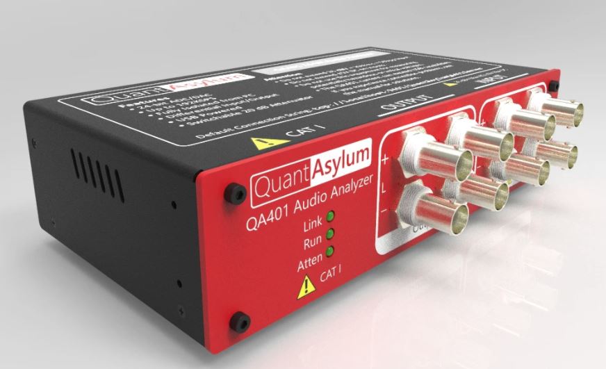
The QA 401 from QuantAsylum (superseded by the QA403) has emerged as a popular, comprehensive audio test instrument in the DIY audio fraternity and the go to instrument in many cases for commercial production testing. It combines a first rate DAC and ADC with a simple user friendly PC interface to realize a fully integrated measurement and characterization system.

In a good set-up, line level distortion measurements of under 3ppm (1 kHz) are readily achievable while the instrument’s noise floor is close to -155 dBV, allowing accurate noise characterization in things like phono and microphone amplifiers. Combine this with a host of built in test scripts and its easy to see why this $450 instrument was such a hit.
However, to get the best results from the QA 401 and it’s more recent upgraded siblings the QA402 and QA403, the user must spend some effort on the measurement set up. I’ve seen many test plots with excessive mains noise, thermal noise or subpar distortion results that have nothing to do with the QA401’s performance, and everything to do with the measurement set-up.
The short presentation below explains how noise arises in a typical measurement set-up, and then shows the reader how to set their measurement system up to exploit the full capability of the QA 401.
Comments
4 responses to “Using the QuantAsylum QA401 for accurate Audio Measurements”
-
Andrew,
Since posting the above, I have seen many YouTube videos on the QA403. So it is much clearer now how everything is connected – thanks!
-
Andrew,
I don’t know if you have time for this but here is a request. Do you mind (in addition to the diagrams you have detailed in the above Power Point presentation) post a short video showing the actual measurement setup for example the KX2 amplifier? I just finished building Jan Didden’s L|A AutoRanger which will be my ‘attenuator’ as such the -20dB attenuator on the input of my QA403 will be bypassed (lowering the noise floor/increasing the resolution) but a slow video showing the entire test setup can help a lot of folks – particularly the types of cables used. My AutoRanger runs on a power bank for absolute lowest noise and least contamination from the power grid. My laptop will of course be run off the battery. I imagine you would recommend that the AutoRanger to also run with differential input and differential output. Thank you!!
-
Claud
I’ve never had this problem. I use Arcol 200W non-inductive power resistors for the load.
Regards
Andrew
-
Hi Chris,
really enjoy the KX2 amplifier that I build last year. Fantastic sound from a relatively small amplifier.
I have in the meantime build some VFA amplifiers with MOSFET’s and BJT output stages.
I have the QA401 (and an old RE201 audio analyser) and is sometime struggling with THD measurements. It seems that the load resistors (both wirewound and high power metal types) can have some voltage dependencies. Is this something you have expirence with? We are taking 0.0005% so it is really low distortion values.BR
Claus from Denmark
Leave a Reply