Your basket is currently empty!
Ground Loops
Updated with new material 7th January 2019

This set of c. 70 slides is the culmination of my experience over a period of about 25 years building power amplifiers and preamplifiers. I first started out in audio around 1975 or 76 as a teenager. Some of my creations were reasonably quiet – through pure luck – and others hummed and hissed horribly. Later, my skills improved dramatically, and especially so after reading one of Henry Ott’s books back in about 1988/89 whilst developing a very high-resolution Digital Panel Indicator for industrial applications at the company I worked for. I then left DIY audio for about 15 years (career, family etc), returning to the subject again in 2005, having forgotten a lot of my practical skills. The path from electromagnetic theory expounded on numerous websites, application notes and posts on various web forums to building quiet amplifiers every time is not easy and requires a bit of practice. The underlying theory can be extremely complex (think Maxwell’s equations), however, with some effort and focus you can quickly master the basics. This set of slides focuses on unbalanced interconnects (aka ‘single-ended’) that use the standard RCA phono connectors, since this is where problems mostly arise.
When it comes to humming and hissing amplifiers, good practical advice is scarce and misguided opinions on the subject easy to find.
This presentation (which will remain a work in progress and be expanded from time to time) is designed to get audio constructors up and running quickly both in the construction/planning phase, but also debugging. It will hopefully also serve as a useful reference for anyone wanting to know a bit more about EMC as applied to amplifiers. One important thing about EMC: you will never stop learning, and finding new problems to solve.
Here is DIYaudio member Ilimzn’s excellent posts on the subject that I gathered into a single document:
ilimzn’s Excellent Posts on Ground Loops
Here is some additional material:
Amplifier PCB Design Guidlines for Minimizing Hum
Some practical guidance offered to a builder on diyAudio:
More Notes On Amplifier Hum Problems
For some practical examples of low noise amplifiers using these techniques, see the nx-Amplifier and sx-Amplifier on www.hifisonix.com
Here are some commercial products that use the techniques described in the presentation: www.ovationhifidelity.com
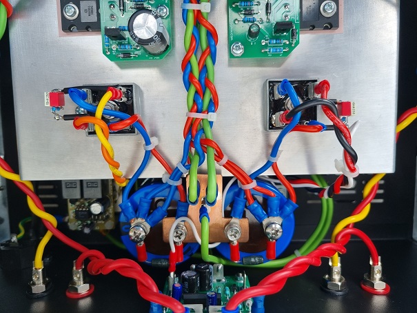
The picture below shows the internal wiring of one of the two nx-Amplifiers I built a few years ago with zero noise or hum problems. The power wiring is tightly bundled, and small signal wiring is kept well away from the transformer and other power wiring. On the PSU PCB, strict attention to the capacitor ‘T’ connection and ‘star’ ground return result in an exceptionally quiet amplifier.

Finally here is a YouTube video of HOW NOT TO DEAL WITH GROUND LOOPS. What is really disconcerting about this is that if you type ‘Ground Loops’ into Google, this will probably be the first reference that comes up on the list.
All the basic safety rules about earthing [grounding] by using a ‘ground lifter’ are completely broken and the noise problem has actually not been solved – they have gone around the problem and made the product completely unsafe in the process – and especially so since this is on a tube amplifier.
The question to ask when dealing with a potential safety fault is ‘What would happen if the live wire came loose and touched on the input jack, or any other metalwork on the product without the safety earth[ground] connected?’ If the answer is ‘it would be at the live potential’ don’t do it!
Never, ever, use a ground lifter in the manner shown in the YouTube video to get rid of hum – its plain dangerous and illegal. Period.
amplifier earthing amplifier grounding amplifier hissing amplifier hum Andrew Russell audio amplifier audio ground loop audio noise chassis common mode noise earth loop earth loops electromagnetic interference electromagnetic radiation electronics EMC EMI engineering filter capacitor ground loop ground loop hum ground loops how to fix ground loops hum magnetic magnetic induction noise rectifier RFI screening star ground transformer what is a ground loop wiring
Comments
53 responses to “Ground Loops”
Hello Andrew,
thank you for your prompt and detailed reply.
Here are some photos:
https://photos.app.goo.gl/uDr393RHwVZ3UARV7
1. Complete amp showing the wiring so far. The wire from the chassis star point to the preamp board goes via the ground break resistor.
2. PSU showing the 0v connection (green) now next to the second set of filter capacitors, instead of at the end of the board like the +/-connections. I wanted to try to emulate your “T” configuration, but you say it’s a bad move.
3. The preamp board with the 0v star point connected to PSU 0v, chassis star via ground break and ground wires to go to input grounds and RIAA preamp. The output connector grounds are also connected here.
I am not a great circuit layout person, so the layouts basically follow the schematics. This means that the +/- and 0v tracks on the preamp go from one end of the board to the other. This may not be a good thing to do?
To your answers:
1. The power supply is regulated and the original 0v connection point on the edge of the board is about 4 cm from the second set of filter capacitors, past the regulators and associated components, that’s why I moved it closer to the capacitors to try to emulate your “T” connection. Should I take the clean 0v from somewhere along that track or at the end? The 0v track is 2 tracks soldered completely together to lower impedance.
2 + 3, The preamp board has inputs on the left and outputs on the right side. I originally had planned to use 0v/signal ground connections at these ends, but changed to a star connection at the volume control ground, to only have one star ground point on the board, after reading lots about grounding.. The input and output ends of the board are 18 cm apart. If I use the ground connections both at the input and output ends, doesn’t this create a loop problem?
Also, am I misunderstanding your comment “… single wire must go to your preamp input ground and from there to power supply clean ground”. Do you mean two connections for input and for output grounds, the second to PSU clean ground?
Or should there be only one clean ground connection to the preamp board and if so where on the preamp is best?
4 + 5. I was planning to use screened cable for inputs and outputs, with the screen connected only at the RCA connector end, with signal grounds all bussed together and returned via a single wire to 0v/signal ground, as you mentioned. Is this not OK? I don’t know how it would work with twisted pairs, would I leave the ground wire disconnected at one end, otherwise there would be multiple ground connections?
6. I hope the transformer location will be OK, I have left the wires long so far to try rotating it for best null, as you suggest in your presentation. The power switch has not arrived yet….
7, 8, 9. All OK.
With my star 0v connection on the preamp board I was using the suggestions of Fast Eddie on DIYAudio and it’s the same as in Dave Davenport’s article on Grounding, Figure 3.2-9, the right hand side example:
https://www.diyaudio.com/community/threads/audio-component-grounding-and-interconnection.163575/I think your suggestions are the left hand side option?
Sorry for so many questions! I thought I had it all sorted out, but I appreciate your help very much! Looking forward to getting it finally wired up!
Thank you!!!
Hello Eric, thanks for your kind comments about the presentation.
It is quite difficult to answer this without any pictures, but I will try below:-
1. For your power supply, where the two filter capacitors meet, bring a short wire (5mm is ok) to a point on your Veroboard. This point is your clean ground. If you connect anything where the two capacitors meet (lets call this ‘dirty ground’) you run the risk of common impedance coupling charging current pulses into your signal ground (aka ‘clean ground’).
2. Your input signal grounds must connect to all the RCA input signal grounds, and then a single wire must go to your preamp input ground and from thereto the power supply clean ground.
3. Your output ground must go separately back to the output ground on the board and from there back to the clean ground. Do not tap it off the input signal grounds
4. Make sure the input wires and the input ground are tightly twisted together to minimise the loop area
5. Make sure the output signal wire and output ground are tightly twisted together.
6. Keep the power supply transformer well away from any circuits – radiated mag fields from the transformer will couple into any loop areas you have and cause noise problems.
7. For your ground lifter, I would take that off the clean ground
8. make sure there is one and only one connection between the chassis and 0V (clean ground). If you have more than one connection, you will get noise. Make sure the input and output connectors are 100% insulated from the metal chassis
9. The safety ground from the mains must go from your input power wire to the point on th4e chassis where your ground lifter is connected – do not use a separate connection in a different location.Hope this helps – please feel free to ask for more clarification if needed.
Kind regards
Andrew
Hello,
I would just like to add to my previous comment that there are 10 pairs of input/output RCA phono connectors.
Also that in point 3., I am referring to the two 0v tracks on the preamp which I used for 0v, They are side by side, and I soldered them together with a complete solder bridge to reduce resistance. (Same on the PSU)
Leave a Reply