Your basket is currently empty!
Very Simple, Accurate RIAA Phono EQ Amp
 Very High Quality Silk Screened PCB’s for this project are available from Jim’s Audio here:-

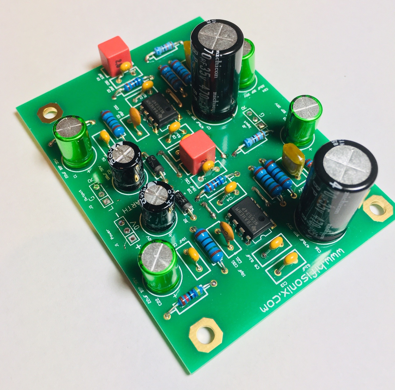
Hifisonix RIAA Amplifier
Here is a simple no-nonsense, accurate RIAA equalizer amp you can easily build. The design uses an all-active topology and is based around an NE5534A low noise opamp. I make no claims for originality but you wont find any voodoo engineering, fairy tales or outrageous claims: It simply does what it says it does in the specification.
A complete stereo board can be built for about £25 ($35), but probably less.
The article provides some background information on the RIAA EQ standard, launched in 1954, and why it came to be the de facto industry standard after about 1960.
To use the PDF PCB layouts below, you must print the documents out on A4. Measure the reference line lengths to make sure they match. You printer should be 600 DPI resolution or better. However, I strongly recommend you just buy the PCB’s from Jim’s Audio – link above. These are very high quality boards, silk screened and gold flashed.
Overlay and 1:1 PDF negative and positive for the EQ board: Hifisonix Phono EQ Amp for Doc114
Optional PSU Overlay and 1:1 PDF positive and negative: Hifisonix Phono EQ PSU106
Gerbers for both the EQ amp and the PSU Hifisonix RIAA EQ Gerbers Hifisonix RIAA PSU Gerbers
Any questions, feel free to email me.
Can I use other op-amps with the Hifisonix RIAA?
Yes, you can. I recommend that you use unity gain stable devices with will not require an external compensation capacitor, unlike the NE5534 used here. You must first REMOVE C2 and C21 – these are the 10pF compensation capacitors. The number of good opamps in 8 pin plastic DIP packages (PDIP or mini-DIP) is unfortunately not what it used to be, so you may have to use a SMD to PDIP adaptor if you want to go down this route.

The plots below are for HIGH gain.
The plot below is of the RIAA noise and distortion at 500mV output at 1 kHz A weighted. This was with board on the workbench, no screening or special precautions and the power supply located about 15cm away. In a metal housing, you can expect about a 30 dB reduction in the 50/60Hz noise. There is quite a bit of noise being picked up from the surrounding CFL lamps etc, but the distortion is almost entirely 3rd harmonic (at -70 dB), with a bit of 5th at about -85 dB.

The plot below is the frequency response after the source signal is passed through a very accurate inverse-RIAA network. The white noise frequency response measurement technique used eliminates extraneous noise sources and is therefore extremely useful. It works by looking at the power spectral density of the amplifier output, which for a white noise source, is constant per octave. If the amplifier response (after passing through the inverse RIAA) is indeed flat, then the overall response will be flat. The A-D was set to 24bits /192 samples per second and the response display set to 30Hz to 100kHz. The RIAA conformity is excellent with no HF peaking and starts dropping off cleanly beyond about 30 kHz.

Comments
18 responses to “Very Simple, Accurate RIAA Phono EQ Amp”
Hi Doug, unfortunately disabling the RIAA EQ is not that simple, because your pre-RIAA vinyls/shellacs will have some sort of EQ. As mentioned in the article, there was a standards battle that raged for a few years, and every record company basically had there own EQ curve. I have not listened to non-RIAA recordings, but from what I’ve seen of the curves, it seems its best just to go with standard RIAA and live with the relatively mild response anomalies. By the way, the expert in these matters is Gary Gallo, who is US based.
https://hifisonix.com/wp-content/uploads/2018/01/Disc-Recording-Equalization-Demystified.pdf
Thanks for sharing your project!
I play a mix of modern vinyl and old 78 RPM shellac records, the latter being created pre-RIAA EQ. Any thoughts on the easiest way to bypass the RIAA components if I wanted to make RIAA switchable?
Filip, you will lose a little headroom, but for the most part I’d say it would be unnoticeable.
If you are using an SMPS, you will have to be very careful with wire routing – keep the MM inputs well away from the PSU wiring. Make sure power cables to and from the PSU are tightly twisted.
for filtering of the MM amplifier, you could try 22 Ohms followed by 100uF in parallel with 0.1uF to ground. Do this on both supply rails.
Rgds
Andrew
Hello,
What is the drawback of using +-12V DC power supply vs +-15V DC ?
I’m retrofitting existing equipment and have Meanwell SMPS power supply with +-12V DC output.
Would I need any additional filtering, having in mind its test report :
https://www.meanwell-web.com/content/files/pdfs/productPdfs/MW/Rq-50/RQ-50D-rpt.pdf
Thanks for your answer.
Regards,
Filip.
Hello Alan,
can you send me a pdf? email it to me at bonsai(at)hifisonix.com
Cheers
Andrew
I have bought the RIAA board from Jims and configuring it in a 309x 220 1U enclosure with ametal screen between the Power/digital area and the preamp.
My quandary is that the signal path transits a relay switching board with 3 other inputs , the tone control board, headphone jack and then the output. As both the RIAA and the tone control board have 15-0-15 power I want to avoid hum loops, so my idea is to remove the gnd connection between the RIAA and relay board to avoid the loop, then tie the RIAA board to chassis.
I have a pdf of the connection plan which I could send to you but unable to on the message frame.
That’s great Alan – hope your build goes well. Any questions, feel free to give me a shout.
Regards
Andrew
Andrew,
Thanks for the reply. I have ordered from Jims via ebay.
I am currently building a gainclone using the LM3886 and separate preamplifier mainly from Elliot sound products projects using my own PCB layouts manufactured by JLPCB in china, but I wanted to produce a separate RIAA front end to be more flexible with what I use.
I apprecite your comments on the SLB and ground planes and will take them all onboard.
Thanks again
Alan Francis RCDD (ret).
Hello Alan, it might just be easier to order the boards from Jim’s Audio via the link rather than try to get your own made. I think they are about $14.29 a set + c. $6 for shipping – I think he has one more left.
Re the ground plane – its not necessary for this type of circuit where the bandwidth is very limited (no more than 100 kHz) and the signals are analogue. For something like an ADC or DAC, a ground plane would be mandatory. Ground lifters are not always necessary and mostly these are used in power amplifiers where ground loops through the Earth and interconnected equipment often arise. given that the source is a phono cartridge that is floating, you should not need an SLB if you follow the wiring plan given in the article.
If you have any other questions, let me know.
Regards
Andrew
I note that you do not include a SLB at the point of ground to chassis. Is that only provided on main Amps and not on preamps. Also The gerber appears to be an old one which JLPCB of china cannot display when uploaded.
Also I note that the PCB is only single sided and that I have always believed that the ground plane on the top side is essential for screening. Is that not so.
Lastly if I substitute The op amps for OPA types is there any change to component values.
Thank you
Hello Felix, glad you like the Simple Accurate Phono EQ! Thank you for your kind comments.
You can increase the gain by removing R4, R7, R8 and R11. In place of R4 and R8 insert a 68 Ohm resistor. If that is still not enough, reduce to 56 Ohms.
These lower resistor values will decrease the conformance to the RIAA EQ curve a little, but it will still sound good.
Regards
Andrew
Greetings, I built one of these phono stages a while ago and it has became one of my favourites. It is well designed and the accompanying technical and assembly article is excellent. Only one slight negative, is there any way of slightly increasing the overall gain from 39 db to 40 db! Regards, Felix Scerri, Ingham, Queensland.
Hello Frits,
you MUST BEND THE LEADS as shown on web page.
Regards
Andrew
Hi,
Is the pcb of the PSU board already updated for the problem with pin layout LM7815?
or do I have to bent the pins of the LM7815 as I read here?
With regards, Frits
Mikkel
Re the last name – done.
Re the Bip capacitors. The reason 35V are specified is that if you have a fault, and the full supply rail ends up across the capacitors, they will not fail.
However, I think 25V should be fine – the kind of situation I describe above is very, very rare
Regards
Andrew
Hi Andrew
Thanks for your reply. I didn’t know my reply would be posted here 🙂 Would you please delete my last name from comment?:-)
Very good alternative and thanks for the links.
Would there be any problems in lovering the voltage to 25v for the bipolar capacitors or would you recommend 35v?
Best regards Mikkel
Hello Mikkel,
thanks for your comments.
On my build I actually used 10% 10nF COG capacitors from Reichelt. I measured them with my capacitance meter and out of the 20 that I bought, 10 were within 2% and all the others within 4%.
If you have a capacitance meter, this is probably a better way to go – here is the link:-
https://www.reichelt.com/gb/en/multi-layer-ceramic-capacitor-10nf-100v-125-c-c3c0g-10n-100-p206836.html?r=1
The other option is to use film capacitors – the PCB will accept these as well. Same story as above – buy more than you need and then select. The film capacitors are much cheaper than COG and will work just as well.
https://www.reichelt.com/gb/en/film-capacitor-10nf-100v-100-c-mmk-10n-100-p206587.html?&trstct=pos_0
regards
Andrew
Hi Bonsai
Thanks for this great guide. It is very well described:-)
I am trying to source the components from Mouser and I have a couple of questions. Hope it is okay:-)
The 10nf C0G 1% capacitors; C5,C6,C17,C18 are for some reason very expensive compared to all the other components at 4 x §2,33. I have found another one with the same specs but in a much smaller physical housing: Mouser part number: 80-C315C103G5G5TA. It is only a little cheaper but would that work or do you have another alternative to the C5,C6,C17,C18 please?
Would there be any problem in using a 22 uf BIP 25v instead of the 22uf BIP 35v as suggested in the mantle? I will only power the RIAA with the + – 15V but not sure if I have to mutilply the voltage when using a Bipolar cap…
Thanks again
Best regards Mikkel from Denmark