Your basket is currently empty!
Hifisonix sx-Amplifier: A 15 W Class A Current Feedback Amplifier
Originally published in August 2012.
Click here to order a set of DS THP PCBs for the sx-Amplifier from Jim’s Audio
About 150 sx-Amplifier PCB sets have been sold, with most of those going on to be built. As you can read about in the PDF below, my class A journey started off after listening to an ancient Musical Fidelity A1 that I repaired for a friend while living in Taiwan. I’ve had many emails from sx-Amp builders who have loved the sound, despite this being a very simple and not particularly low distortion amplifier. If you are new to DIY audio, this is probably a good as any place to start.

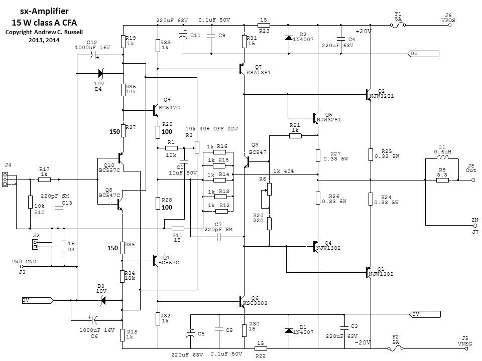
The hifisonix sx-Amplifier is a low component count current feedback topology (CFA) design that delivers 15W RMS in class A into an 8 Ohm load (about 25W peak in class A) and around 25W RMS into 4 Ohms in class AB mode. The design uses readily available components, achieves very wide bandwidth, along with fast rise and fall times. Distortion is low compared to competing designs (e.g. JLH’s 10 Watter from 1969, or Jean Hiraga’s 20 W class A), thanks to the availability of modern bipolar devices, and the use of LTSpice to optimize the design.
You can down load the full pdf article here The-sx-Amplifier-V2.10
Here is an Excel file that contains the BOM lists, including Mouser part numbers for the sx-Amplifier (covers both the double sided THP PCB version ABOVE and the new single sided PCB version discussed below):-
sx-Amplifier-BOM-Excel-September-2016
I have had a lot of requests for PCB’s and/or people indicating they would like to etch their own boards. To support these requests, I’ve created a second layout that is singled sided and more amenable to home etching. (The PDF file scale is 1:1):
Here is the component overlay for the single sided sx-Amp SS sx-Amp Top Component Overlay
Here are the Gerbers for the single sided sx-Amp Single sided sx-Amp Gerbers
Pop Alexandru, also known as Alex MM on diyAudio.com has also kindly produced a set of single sided PDF layouts below that closely follow my DS THP version. He has produced both mirrored and non-mirrored versions. His boards are neater than mine! Thank you Alex!
SX-AMPLIFIER TOP SILK SCREEN MIRRORED
SX-AMPLIFIER SINGLE SIDED COMP OVERLAY
SX-AMPLIFIER SINGLE SIDED BOTTOM
SX-AMPLIFIER SINGLE SIDED BOTTOM MIRRORED
Note: there are no single sided PSU layouts. If you build the sx-Amp using single sided PCB’s, and your own PSU, do not forget to fit your finished amplifier with a Zobel network of 0.1uF and 10 Ohms in series from J7 to the 0V star ground on your PSU. If using the DS THP PSU board from Jim’s Audio, the Zobel network is located on the PSU board. Just follow the wiring up instructions in the writeup.
Note: the component numbers and BOM list are all the same for the single sided PCB but with the following changes: J2 is removed. C2 becomes a 16V 10uF through hole capacitor (C1 remains a 1206 10uF 50V MLCC SMD device); Q3 becomes a BC547C.
If you have any questions or concerns, please post your comment up here, or on the DIYaudio forum here: https://www.diyaudio.com/forums/solid-state/236522-sx-amp-nx-amp.html
Here is diyAudio member Thimios from Greece showing his fantastic sounding sx-Amplifier
_____________________________________________________________________________
The sx-Amplifier: A 15 W Current Feedback Class A Amplifier
Jean Hiraga’s 20 W class A design became something of a cult amplifier in the 1980s in the audio community and constructors from Europe, Australia, Japan and the USA praised it’s sonic performance. In that design, Hiraga used a much simplified (I’d call it sparse, or ‘stripped down’) current feedback amplifier (CFA) topology and low feedback to create an amplifier that was described somewhere as sounding ‘liquid’ and ‘tube-like’. Hiraga has always been noted for his minimalist, idiosyncratic designs, and comments about the sonics aside, I was attracted to the simplicity – only 8 transistors in the original and a handful of discrete components (excluding the power supply of course) for a complete class A amplifier. Distortion was by any standards very high, topping out at about 1.8% at the rated power into 8 Ω, although he seems to have indicated it was of the ‘good variety’ due to its harmonic structure. However, Hiraga’s amplifier (rated at 20 Watts per channel into 8 Ω) was the product of 1980’s know-how and device technology. I found myself wondering what I could cook up with today’s components and the insights afforded by circuit simulation tools that were unavailable back in the early eighties. I did quite a bit of research on Geoff Moss’s excellent ‘the class A amplifer site’ (tcaas) and Rod Elliot’s ESP site and the Death of Zen (DoZ) amplifier, modelled after JLH’s classic 10-Watt design from 1969. Compared to the 1980s, we now have some really good power transistors, and there is no shortage of cheap good quality small signal devices either, other than the ultra-low noise small signal bipolar and JFETs from Toshiba in Japan of course, which are now discontinued.
Looking at the reprint of JLH’s original 1969 10 W class A design, it is immediately apparent that the distortion vs. frequency graph at 9 W output is flat all the way out to the measurement limit, which was beyond 20 kHz. In a conventional Voltage Control Amplifier (VCA) class AB topology, when driving a load that causes the output stage to exit the very narrow class A bias region (ideally set at .026/Retot where Retot is the total output transistor emitter degeneration resistance including the reflected base resistance and typically ranging from 0.1 Ω through to 0.47 Ω), distortion kinks upwards at 40 dB/decade, with the kink point a few hundred Hz up to a few kHz. Distortion increases at 40 dB/decade, arising from the fact that the amplifier loop gain beyond the -3 dB point is decreasing at -20 dB/decade, while the THD contribution doubles with every octave because with every doubling of frequency, there is a doubling of cross over events, and hence distortion.
The shape of the distortion curve over frequency tells us something about the nature of class AB amplifiers when required to move from their class A region into class B – feedback can only do so much to reduce the distortion, and if that feedback (loop gain) is already decreasing at 20 dB/decade within the audio band, you simply have to accept the uptick in the distortion vs. frequency plot. JLH’s output stage design was class A of course, and so did not have to contend with crossover distortion, and this is the fundamental advantage of class A over class AB. The major distortion component in any competently designed class AB amplifier is the crossover distortion, and if that can be removed as a factor, there are significant performance and sound benefits to be had. At low frequencies (i.e. below about 30 Hz), the distortion on JLH’s amp rose rapidly because of the electrolytic coupling cap between the output and the speaker. Later enhancements of his design did away with the output coupling capacitor at the expense of a split rail supply and output offset adjustment.

The sx-Amplifier is a thoroughly modern take on the class A genre that employs CFA topology, 30 MHz Ft output devices and features a – 3dB bandwidth of 540 kHz, along with slew rates of 140 V/us. This is a very smooth sounding amplifier, suited to jazz, classical and acoustic material in general which should be married to speakers with efficiencies of 92 dB/W or better if one is after realistic concert hall sound levels – however, I used mine whilst in Asia with my B&W 703’s, which are rated at 89 dB/W, in a modest sized listening space and found that satisfactory volume levels were easily attainable.
In the design you see here, I had the transformer specially wound by ‘PowerStar’ in Taiwan and it features a screen and GOSS band for the best noise performance. Careful attention to layout and wiring have resulted in an exceptionally quiet amplifier. What does it sound like? As mentioned earlier, this amplifier is best suited to classical, jazz and acoustic material – because of the limited power on tap, its not really suited to rock or material that demands high power.
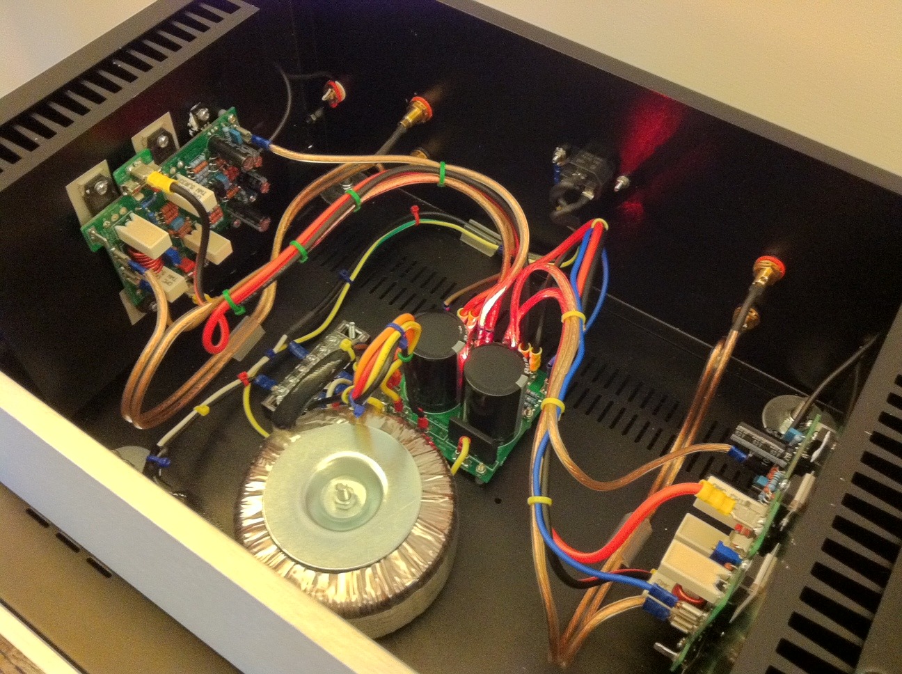
The photograph below is of the second build I did of the sx-Amp.

This is the sx-Amp I ended up using up until the kx2-Amp arrived some 10 years later in 2022. Incidentally, I built one of the nx-Amplifiers into a similar chassis.
I have to admit I started this project with some apprehension about what a small amp would sound like – especially since I am used to listening to a big amp (250 W per channel which you can read about here Ovation 250 Amplifier and a 180 Watter called the e-Amp ). Why design a 15 W class A amplifier, and especially one that is decidedly minimalist, after two big, complex, powerful, high performance ones? Well, there are a few reasons. Firstly, designing single digit, or sub 1 ppm distortion amplifiers can provide a rewarding intellectual experience, if only to later be thwarted by practical execution that impacts both performance and build aesthetics. Secondly, reductions in distortion below about 0.5% offer little or no further improvements in the perceived sound quality of an amplifier in controlled testing and there is a lot of academic material in support of this contention. Anecdotally, Nelson Pass has built a name for himself with class A amplifiers that for the most part never see the south side of 0.1%, and yet are highly rated by the cognoscenti. What about power levels? Big amplifiers sound wonderfully at ease with themselves – they are unflappable and handle music dynamics well. Low power amplifiers, like the sx-Amp under discussion here, really need to offer something unique to justify the effort in construction, and exploring this territory is the 3rd reason for undertaking this project: is there a magic class A sound that makes building something like this worth it?
Speakers are notoriously non-linear often 2 to 3 times higher than the 0.5% I quoted above. Now, none of this can serve as an excuse for badly designed, sloppily engineered, high distortion amplifiers. We know that the ear is much more sensitive to some types of distortion (crossover for example) and to higher order harmonic content in particular. If these things are taken as considered inputs into the design process, we then have some latitude in design philosophy: Challenging, all out, ultra-low distortion designs, or something a little less demanding, but that ticks all of the right boxes given our knowledge about how the ear/brain system works and therefore sounds good because we avoid the major pitfalls, and is FUN TO BUILD! This is exactly where the sx-Amp is positioned.
Once testing and set up were completed, I was very excited to hear what this thing could do. For initial listening I chose a few classical CD’s – a Lexus classical CD (freebie), Julian Bream ‘The Ultimate Guitar Collection’, a wonderful ‘LSO Live’ sampler from Hi-Fi News, A Philips Sampler from the 1990’s ‘Introducing Mozart’, followed by two jazz CD’s: Michel Petrucciani’s ‘Both Worlds’ and ‘Time Out’ from The Dave Brubeck Quartet.

Pictured above is the very first sx-Amplifier I build in 2012 while living in Japan
I’ve had a Hi-Fi News LSO sampler for about seven or eight years. The tracks date from performances made between 1999 through 2002. All tracks superbly recorded with tremendous space (holographic) and dynamic range. The sx-Amp produced a wonderful three dimensional sound stage that extended well beyond the speakers, very deep and layered front to back. If you are ever looking for a classical demo CD – this has to be it! To be sure, a big part of this is the quality of the recordings, but no doubt the class A magic also played an important role in what I was hearing. Strings have that ‘bite’ to them in their lower registers and the top end shimmers marvelously; brass has the leading edge snap followed by the tizz that you only get from a really good recording played through a sympathetic signal chain. The top end on this amplifier is very beguiling without any hint of harshness and the overriding sensation is one of smoothness and relaxed detachment. The scale on the Brahm’s piece (‘Denn Alles Fleisch Est Wie Gras’) was very well reproduced which was surprising to me given the fact that only 15 W was on hand.
Up next was a double CD collection of Julian Bream recordings covering the four decades from 1959 through 1982. Some of the early recordings are a little noisy (tape hiss) but the sound is very spacey and the notes wonderfully rounded and resonant. My favourite is disc 2, which was recorded in 1982/83 and consists entirely of solo guitar and lute pieces. Here again, the sound staging and recording venue are beautifully captured and easily re-created by the sx-Amp.
Philips – when they were still in the music business – released a huge Mozart collection in about 1992 or ’93 and I’ve had the collection sampler about 20 years. There are 19 tracks and the recordings vary from good to outstanding. One of my favourites is the horn concerto in E-flat. I think Sir Neville Mariner’s recording is one of the best – the horn really floats out above the orchestra and the reverb and scale of the recording space make for an incredibly immersive experience. The whole piece is energetically played – I have found some other recordings, because of the arrangements and the conducting no doubt, to be laborious, plodding and acoustically flat by comparison. This recording is one of the better ones on this CD – I think some of the tracks are a little bright (maybe that’s just because it’s Mozart!), but the horn concerto is beautifully balanced. The sx-Amp presented a very smooth, rounded sound with no hint of harshness. The layering front to back was very precise, and the left to right sound stage wide, though not as far beyond the edges of the speakers as the LSO CD – a wonderful listen however.
Dave Brubeck’s ‘Time Out’ always amazes be because it was recorded in 1959 (like some of Julian Bream’s recordings mentioned above) and you can hear the tape hiss and one or two other minor imperfections, and yet the sound is absolutely palpable. This is a re-mastered re-release but is has lost none of the quality of the original. The cymbals, always a very difficult sound to reproduce accurately, are as smooth as silk and seem to hang in the air – I’ve heard more recent recordings where they sound flat and lifeless by comparison. Paul Desmond’s alto sax and the bass, played by Eugene Wright, have some wonderful space around them on ‘Strange Meadow Lark’, one of my favorite tracks on this CD. The sx-Amp is able to convey the sparseness of the music, and the recording, reproducing the very wide and deep sound stage – very three dimensional. Again, as with the other recordings, there is a sense of a very relaxed, effortless, smooth sound.
Most of the tracks on Michael Petrucciani’s ‘Both Worlds’ are spaciously recorded and the sound staging is good. The sx-Amp again did a great job of conveying the space around the musicians. There are a few tracks where the brass is set well back in the mix and this lends great depth to the recording, although in general the sound stage is not particularly wide. I was pleased to discover the sx-Amp could give the same sensation of depth as the Ovation 250 and the e-Amp, which offer a first class listening experience in this regard.
I have not said much about the bass performance of this amplifier. You’d expect a 15 W amplifier like this lack the scale of higher power examples, but I was pleasantly surprised at how realistic the bass reproduction was. Importantly, it had weight and the notes were well sustained. I’ve heard a lot of systems where the bass is very lumpy. No doubt the speakers and recording play a role here, but if there are any shortcomings in the amplifier’s ability to reproduce bass notes exactly as they are recorded, or drive the speakers effectively, you can bet the overall sound is going to be disappointing. Bass plays an important part in imparting space and weight to a piece of reproduced music – this is one of the reasons sub’s often seem to bring a system to life, despite the fact that they are producing little or no acoustic output above 100 Hz or so.
My B&W 703s are moderately efficient at 89 dB/W, and they are a relatively easy load to drive, so getting reasonable SPLs out of this set up is doable. The sx-Amp output stage is hefty, so up to the limits of the power supply voltage, it has no problem delivering plenty of current when required.
Of course, this is not an amplifier for a ‘head banger’ music set-up – the sx-Amp is better suited to jazz, classical chamber and acoustic music. If you want 3D sound staging and shimmering highs on strings, this amp does it. If you have some efficient horns or suchlike (96 dB/W and above), then 15 W is going to allow you to get realistic orchestral levels, although I never found this to be an issue on the material I tried on my speakers as described above.
The sx-Amp achieved all of the goals I set out when starting this project: a simple design using modern, readily available components with wide bandwidth and speed (i.e. fast rise/fall times). The design goal called for wide loop gain, which was achieved through the selection of the CFA topology. I was not expecting any huge surprises sonically, but after completing a few hours of listening tests, I can say the sx-Amp is wonderfully smooth, open and has a very relaxed, non-fatiguing sound – not what I was expecting at all, and a really pleasant surprise.
The earlier designs from JLH and Hiraga are highly regarded and as of 2025, JLH’s is over 55 years and Hiraga’s close to 45, but they have clearly stood the test of time as constructors return time and again to their simplicity, circuit elegance and sound. Nelson Pass’s mosfet based designs, some of which date back 35 or 40 years, feature simple, elegant circuits, and much of the effort is focused on the harmonic structure of the distortion – his class A amplifiers are also legendary within the DIY community and noted for their sonics.
I hope that the sx-Amp joins this august group of DIY amplifiers, and emerges as a ‘modern take’ on what is ultimately a very specialist and esoteric audiophile segment: minimalist low power class A amplifiers that focus on listenability.
Comments
103 responses to “Hifisonix sx-Amplifier: A 15 W Class A Current Feedback Amplifier”
Vinnie,
I am very sorry. The PCB is incorrect – R4 must be 15 Ohms, and J2 is normally shorted out (only use it to break a hum loop).
you should let the heatsink get hot, then adjust the offset for zero. Also, make sure your source has no DC offset.
I will put an error message on the sx & nx thread about this – it is not Jim’s fault – its an error on my PCB overlay.
J2 shorted. It works. I have -38mV output, but seems not yet centered. Turning the trimmer offset increases in far from zero.
R4 is 100kAlan,
unfortunately you cannot do this with the sx-Amp as it will lead to increased distortion.Thanks for your feedback.
Andrew
Please short out J2 – i.e. put a link of wire across it. Can you tell me what value you have for R4?
Hello Andrew,
no input connected.
There is no bridge across J2, is that the meaning of shorted out?
R30 and R31 are 15 ohms, as indicate in the schematic and on the PCB, not 33 ohms.
C7 is 220 pF Polystirene.Let me know.
Vinnie
Vinnie, when you are doing these readings and set-up, I assume you have no input connected. Is J2 shorted out? Can you confirm the value of C7 is 220 pF?
Please also measure R30 and R31 – should be 33 Ohms
Dear Sir, is there a possibility that the SX amplifiers class A output could be increased to say 25W RMS into 8 ohms ( higher bias or supply rails) before entering AB.
Thank you for giving this design to the DIY community.
Best regards
AlanHello Andrew,
voltage across R30 is 621mV, across R31 is 594mV.
Across .33ohm resistor there are 185mV, 186mV, 185mV and 187mV.
I bought TIS from Farnell. Due to the fact that seems impossible to find the same hfe range, have been changed with 2SA 1220A/2SC2690 (as indicated in the DYI forum). Thiese transistors have been strictly selected.
Output BJT are MJL1302/3281. I bought these transistors, including the TIS 1220/2690, from a reliable supplier in Poland.
All other components (input transistors are original Philips) have been bought from a historical shop in my town in Italy.
Vinnie
Vinnie, from the voltages you are measuring, I don’t think its the front end.
1. Please measure the voltages across R30 and R31
2. Can you confirm what the voltage drop across the output stage emitter resistors is? Please measur across each of the four resistors.
3. Can you confirm what transistors you are using for the VAS and where did you buy them (I hope not from ebay!)Andrew,
I measured the voltage on the resistors and I have: 136/137 mV across the 100 ohm resistors, 148/125 mV across the 150 ohm resistors, 1.234/1,213 Volts across the 1K resistors.
It’ clear that there is a problem on the 150 ohm resistors.So I decided to work on the second pcb: I measured the resistors value and everything is correct.
Arrived at this point, I decided to select again (for the third time, the input transistors. A very strict selection has been done: all the transistors measuder an hfe of 511: I this for the hfe could be considered a perfect match.Are you curious to know the output? Again it is impossible to bring to zero the offset output , ranging from -634mV to about – 1 Volt.
My conclusion is that there is a problem on the PCBs built by Jims or on the PCBs layout. The same problem on both, after changing the input stage three times. And exactly the same offset problem.So please take into consideration this possibility, and let me know if another DIYr experienced the same problem.
During the next days me and a friend of mine will check the Whole PCB to find where the problem is.
Rgds
Vinnie
Vinnie, those are all correct.
Can you measure the voltages across the 100 ohm resistors and the 150 Ohm
resistors.can you also measure the voltages across the 1k resistors.
Rgds
Andrew
Hello Andrew,
I did the test you proposed.
– R36: 147,5 OHM, R37 147,7 OHM;
– R28: 98,1 OHM, R29 98,4 OHM;
. R32: 993OHM, R33 990OHM;R1 conmmected to R3, related to GND, measures from -9,97 Volts to + 10,04 Volts
From the negative to the positive outoput offset starts at -0,524 mV (-9,97mV on R1) and ends at -0,908 mV (+10,04 V on R1).Across R23 there are 887 mV, across R22 860 mV.
The input transistors of the diamond buffer (Q8 to Q11) are selected only by hfe, between 460 and 474 circa. They have not been selected by VBE. But I cannot think that this stage is so critical if the input transistors are not VBE matched …
Vinnie
Vinnie,
please check and make sure
– R36 and R37 are 150 Ohms
– R28 and R29 are 100 Ohms
– R32 and R33 are 1k
– measure between R1 where it connects to R3 wiper, and make sure you can adjust it from -10V all the way to +10V.If any of these resistors are the wrong value, you will get the problem you are mentioning.
Measure across R23 and across R22 – both should measure 800mV +- 150mV – they should both measure almost the same.
Bambadoo, thanks for highlighting these discrepancies. I will update the document in the new year. Your build looks very good by the way- impressive speakers as well!
Hello Andrew,
the problem has been partialy solved.
I made a mistake because I put 0.15ohm resistors instead of 0.33ohm as indicated.The poblem now that seems impossible to adjust the zero offset.
Zeners are selected (measuring on 10,01Volts, and 9,97 volts), TIS are strictly selected and BC550C/BC560C (instead of 547/557) have been selected. I also changed these transistors, whose Hfe is amont 465 and 474.How is possible to adjust the offset (the minimum now is -0,543Volts, and decrease to 1 volt).
Can you help me?
Thanks
Vinnie
[…] audio (fra ebay) startet å produsere pcb på lisens fra bonsai var valget lett. Mer info er her. Ovation sx-Amplifier: A 15 W RMS class A Current Feedback Amplifier The Ovation sx-Amplifier is a low component count current feedback topology (CFA) design that […]
I am also building the sx amp. There are some issues between the jims audio pcb and manual. I have written on the diyaudio.com thread. There are no bc847 smd component. Just bc547 through hole.
I think R20 is wrong on the pcb. I think it should be 1k instead of 220r.
The bourns pot I think has wrong marking on the “turnin” knot compared to the marking on the pcb. (checked with a finished built sx)Vinnie,
That is definitely not correct. The boards from Jim’s Audio are the same layout (Gerbers) as my ones. R21 is in the correct position. The output stage current is directly regulated to 700 mA per pair using this technique. Please make sure R21 and R20 are 1k Ohms each and you must adjust R6 for MAX resistance – i.e 1k. You must measure across the pot – don’t just rely on turning the pot clockwise as if it it in back to front, you will actually be turning it the wrong way.
Make sure the emitter resistors are 0.33 Ohms.
Also please check (i.e measure) Q3 BC847 – If this is incorrectly installed as PNP then you will also get this problem.
Hello Andrew,
I bought from jims audio the new sx amplifier pcb.
I built the boards selecting all the components, paying attention also to the construction.
I checked the boards following your instructions but powering +/- 25volts it’s impossible to regulate the idle current that immediately rises to 4 amperes.
The problem happens in both the pcb.
Did someone build the new pcbs from jims audio? Do you have feedbacks regarding the same problem? Or can you help me? Could be a problem on the pcb? Or something that occurred to the bc547 of the idle current? I checked almost ten times the components and everything is correct .
I hope to have a feedback from you.
Thanks
VinnieHi,
Is it possible for you to eliminate the nauseating and erroneous “power RMS” throughout your website??
Check AES for the correct terminology for power.
Regards.So what would you have me use?
Average power
Peak power
Music power
Instantaneous power
Peak average power
Peak music powerRMS power is universally understood and that’s what I will continue to use.
Hello Ratheesh,
Vinnie from Italy just asked how to use a nx-Amp board to make a sx-Amp – see my reply to him.
Separately, I will ask Jim’s audio if they can do such a board.
Thanks for your interest in the sx-Amplifier.
Regards
Andrew
Hi please make available of sx-Amplifier PCB boards from your side it will be really nice like you did for nx with jims audio
Thomas, sorry for the late reply.
For L1 I will put something up in the next few days. Apologies for this I have been very busy on budiness these last few weeks.
For the pot – yes I think it should be fine. The main thing with pots is to keep the DC off them, which is what I show in the ‘How to add a volume control’ at the back of the write-up.
For the pre-out, it is possible – I need to think about it. I assume you want it to come from the power amp output?
Rgds
Andrew
Hello,
I have been trying to find a decent quality 5k log pot, but the RK27 seems to be only available in 5k as mono or quad. I found a few 5k stepped attenuators, but they were costly.
Eventually I found a 5k PEC molded carbon pot. Do you think this will be any good?I was also wondering if it was possible to add a pre out for an active subwoofer?
Finally, I am looking forward to see your description/picture on how to wind the L1 inductor. By the way, where were you planning on posting this?
There’s no hurry, but please don’t forget.Best regards
ThomasThank you, Andrew. You have been very helpful.
Best regards, ThomasHello Caveman,
Unfortunately I don’t have any ideas where to get matched pairs ( ie same gain grade).
My suggestion is you put a post up on DIY Audio – a lot of guys on the forum know where to get parts from.
Regards
Andrew
Thomas,
Your Schiit DAC should be able to drive a 5k Alps pot very nicely.Regarding J2 and and C2 – you are correct in the changes you note for the single sided board (I probably need to add these points in the write-up)
For L1, you have to wind this yourself. I will post up a picture and how to do it this week end. It’s very easy.
Thanks for the advice Andrew,
I will go for the 5k or 10k RK27.
I am using a Schiit Modi 2 DAC, but I am not certain what loads It’s able to drive.
Its specified with Max Output: 1.5V RMS , Output Impedance: 75 ohms.I will use the single sided board, with double sided PSU. I think I will just order them from http://www.futurlec.com.
Before ordering the parts I was hoping you could clarify a couple of things before I place the order.
1. I can use the same parts as in the SX V2.09.pdf BOM, but remove J2. C2 becomes a 16V 10uF through hole capacitor. Q3 becomes a BC547C.
As described above, right?2. BOM part 16 (L1): 0,6uH Inductor – Could you please give me a part number or link, I am having some trouble finding this part.
Best regards
ThomasHello Thomas,
you can use A100452CT-ND.
For caps, 50V or 63V part will work equally as well.
With respect to your question about the buffer and volume control: The connection is shown at the back of the sx-Amplifier build document – that will work fine – no need for a JFET buffer.
I recommend a 10k LOG taper ALPS pot (RK27 Blue Velvet is what I normally use – you can get them for about $15 USD on eBay). If your source can drive a 5k load, then a 5k pot is even better. Typically, most CD players will be ok driving 5k Ohms or higher.
re the PCB – I think the single sided board will be easiest and cheapest to use. The DSTHP board is probably best for group buys on DIYaudio because doing them 1 off is expensive unfortunately – this is why I designed the single sided version but you will have to etch it yourself.
For tone controls, unfortunately these cannot be added to the sx-Amplifier – might be a separate project I have to look at in the future.
Oh, and sorry about my post asking for the BOM excel file. I now read in the thread at diyaudio that you deleted it and referred to the BOM in the V2.09 SXpdf file instead.
A couple of things regarding this BOM:
C8, C9 is listed with label value 50V – But Mouser lists this as 63V. Is this the correct part?
J2,J4,J5,J6,J7,J8 is listed with part number A100452NCD-ND, which I can’t find anywhere.
However, Digikey has a part with number A100452CT-ND(same as in PSU BOM). Is this the correct part?Best regards, Thomas
Hello Andrew,
The A21a drove the LS3/5a’s all the way to the limit I think. These speakers are not capable of particularly high levels of loudness, before the woofer bottoms out. I have been looking for a class A DIY project for some time, mainly Pass and Hiraga, before I found your design. I was very impressed by your design philosophies, boiling down all the relevant topologies to a simplistic but modern design, but most of all by your thoroughness in documenting them so that even unexperienced people like me could take some of it in.
My mind is now set on the SX. I don’t suppose there are any finished PCB’s available for this yet?As mentioned, I don’t have a lot of experience, so would you recommend using the single-sided or the double-sided approach? I have a brother with a lot of experience, so he can help me out if I get stuck, but I would really like to try to do this on my own.
As to my music preferences, I listen to mostly anything -if it’s good:) I have worked as a consultant in a HiFi store for over 20 years and learnt to appreciate a wide variety of music.
AS mentioned in my earlier comment, I would really like to implement a volume control.
I have now, very briefly, read a little about your UBx buffer design, and I think this is the way to go. Are there any PCB gerber files in the pipeline for this project?I am a little torn, however, because ideally I would like to have tone controls. I quit working at the HiFi store some years ago, making it possible to come out of the closet and say that now:) Actually, with the LS3/5a’s, normal tone controls is of little use since the woofer bottoms out too easily if you boost the bass at the standard boost frequency. But I found that driving the speakers with an older NAD design there was another option, namely “Bass EQ”. This had, strangely, almost no impact on the woofer excursion, but gave me just that little extra I wanted. According to a NAD engineer visiting our store this was simply a 6db boost in the 40-60hz region, if I remember correctly. I guess there is no way to do this passively and implement it in the UBx design?
If not, I am considering making a very simple preamplifier with bandaxall tone controls instead. -If I can find a suitable DIY project.
Sorry for my long windedness, but the HiFi-nerd in me has been stirred from it’s slumber.
Best regards, Thomas
Hello Thomas, no problem.
I proposed 96 dB/W if you want high SPL levels. There is nothing wrong with using the sx-Amplifier with lower efficiency speakers – you just wont get the loudness level you would get with high efficiency speakers. This point will apply to any low efficiency speaker – its not related specifically to the type of amplifer, but the avaiable power. The peak class A output on the sx-Amp is about 28 W into 8 Ohms – so its at the same level or a bit better than the Sugden A21a, while into 15 Ohms its about 15W peak.
What kind of music do you like to listen to?
Hello again,
It seems the SX BOM excel file link is not working. Just thought I should let you know.
Best regards
ThomasHi,
I am sorry to bother you, but I am looking for a class a amplifier project for my LS3/5a’s. Years ago I owned a Sugden A21a which is the amplifier I have been most satisfied with in combination with the LS3/5a.
As you probably know these have very low sensitivity and high impedance.
Above it is suggested that the SX amplifier should be “married to speakers with efficiencies of 96 dB/W”, but is there any reason why the SX amplifier should fare worse than the A21a? These amplifiers has a very similar power rating, but I am guessing you know this as well.Finally, would you say that the SX amplifier would work well with a passive volume control as per appendix 6 in your pdf?
Best regards
Thomas, NorwayCan’t get the KSA1381 and KSC3503 in the same grade.
Some DIYers must have exhausted the stock in Rochester
Electronics in 2013. Any chance of Plan B for late comers?Thank you.
ok – have a try now – it should be fixed!
Just with your site.
I need Gerbers for the double sided THP sx-Amplifer board and the PSU board.Just try to download a PDF doc from any other site – is the problem you have only with my site?
Which another site?
Hello Johnny,
It’s working from my side. Can you try to download from another site. Otherwise PM me and I’ll send the files direct to you.
Still not working.
Johnny, I am travelling now – I will take a look tonight.
Try to download Gerbers for the double sided THP sx-Amplifer board sx-Amplifier and the PSU board sx-Amp PSU board – but not working.
Not Found
You tried going to http://hifisonix.com/wp-content/uploads/2013/11/sx-Amplifier.zip, and it doesn’t exist. All is not lost! You can search for what you’re looking for.
thank you very-very much mr russel. i’ ll waiting .the layout. and imagine listening sx amp. REGARDS
Hello Wahyu,
I will relay the board out in the next week or so for single sided (it’s double sided now) and post it up on PDzf. Many people are asking for sx-Amp boards, but they need single sided to etch by themselves. Please wait a few days.
Regards
Andrew
hello mr bonsai. iam from indonesia its hard to get sx amp pcb.any solution.i cannot use pcb software.may i get pcb layout on pdf ,in this 3 month really want built this masterpiece.if you dont mind.sorry for bad english regards
Hello Vladislav,
The designs are for DIY – there are no completed products for sale.
The nx-Amplifier has a PCB available from Jims Audio (see the link on the website) which is about $25 for a set of two amplifier PCB boards and a PSU PCB. There is a builders thread in DIYAudio.com under ‘sx and nx- Amp’
Thanks for your interest.
Rgds
Andrew
Dear sir,
Could you please tell me is your site just for information or you can make the amplifiers for sale.
Regards
Vladislav
New York
Leave a Reply