Your basket is currently empty!
Hifisonix Ripple Eater PSU for the sx and kx-Amplifiers
The PCB’s are through hole plated and silk screened and are available from Jim’s Audio here:
Ripple Eater PSU for kx and sx Amplifiers
(please note these PCB’s are not available from the Hifisonix Shop)
Here is an Excel file with the BOM: Ripple Eater PSU BOM
The BOM is provided for assistance – always carefully check the part numbers and quantities before ordering.
Here is the BOM if the link above does not work

Introduction
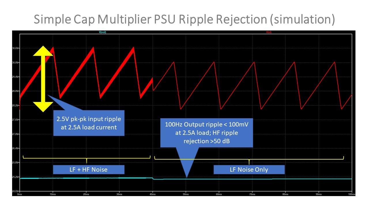
Here is a very simple capacitor multiplier PSU aka ‘ripple eater’ for the sx or kx-Amplifiers. The LTspice simulated ripple rejection at 100 Hz is about 65dB and at 10 kHz it is 85 dB. These figures assume you have a 2.5A load and also include the on-board filter capacitors on the amplifier modules themselves (220uF per rail on the sx-Amp and 1000uF per rail on the kx-Amp per amplifier module).

Class A amplifiers draw heavy quiescent current from their power supplies, and this gives rise to significant amounts of mains related ripple that will affect the amplifiers noise performance. VFA amplifiers generally have better LF PSU noise rejection than CFA’s, but it can still be a problem with a class A VFA.
A further benefit of this supply is that the radiated mains noise from the PSU to amplifier module wiring is greatly reduced because you will be supplying close to DC into the amplifier module local reservoir capacitors, so the associated mains ripple charging currents are very low. Low frequency (because the HF currents will be provided by the local on board reservoir capacitors – 220 uF for the sx-Amp and 1000 uF for the kx-Amp) signal related currents will still be flowing in the wiring of course, so you have to pay careful attention to layout, how you dress the wiring, loop area minimization and common impedance coupling issues – you can read more about this in ‘How to Wire -up a Power Amplifier’. Nevertheless, this PSU goes a long way to making sure your finished amplifier can be as quiet as theoretically possible. When combined with the 50~60dB mains noise rejection of the actual amplifiers themselves, the noise levels on the amplifier output will be down as much as 100 dB which is an outstanding result by any measure. At HF, the performance will be even better, and that is important for the amplifier sound in the mid and high range.
The series pass transistors (8A MJE15032/33 devices) are designed to be mounted underneath the PCB with their tabs screwed to the amplifier chassis base using the appropriate thermally conductive insulator (same mounting technique as the main rectifier D4 as well but you do not need the insulating washer on the rectifier – only some thermal grease). Each pass transistor will dissipate about 10W in a stereo set-up delivering full output power into the loudspeaker load.
In normal operation, you will drop ~2 volts across each pass transistor, so if you want an output of say +-27 V, the loaded DC voltage into the PSU should be 29 V. Note carefully as well, this power supply does NOT regulate the output – it will track the raw filtered DC voltage, but remove the ripple hence the ‘ripple eater’ name.
How Can I use Ripple Eater PSU on class AB Amplifiers with Higher Supply Voltages?
You can use this ripple eater power supply as is up to +-35V. You can also use it on amplifier with higher supply voltages up to +-50V. However, you must change the filter capacitors to 50 or 63V types (this is C1 and C6 in the schematic). In a class AB amplifier, you can use values that are about 3x LOWER than you would on a class A amplifier – so about 15 000 uF at 50 or 63V would be correct. You must also change C5 and C7 to 50 or 63 Volts. Finally, change R5 and R6 to 10k each. Note that the Ripple Eater PSU is not suitable for amplifiers with power supply rails much above +-50V because the series pass transistors (Q1 and Q3) are rated at 8A continuous and this places an upper limit on the output power.
Can I Increase The Power Handling Capability of the Ripple Eater?
Yes – you can.
Replace Q1 with an NJW3281 or a MJW3281
Replace Q3 with an NJW1302 or MJW1302
The PCB mounting holes for Q1 and Q3 will NOT accept the larger types above, you must run short wires from the PCB to the larger suggested power transistors above. Do not mount the offboard transistors more than 10cm away from the PCB. Make sure the transistors have a good heatsink – again, I recommend you mount them to the chassis if it is constructed of 3mm thick or more aluminium.
Remember, the transistor collectors must be insulated from the chassis – use a suitable silicon heatsink pad
Performance
The graphic at the top of this post gives some indication of the performance (simulated) of the ripple eater supply. I used a ripple eater on the e-Amp to clean-up the supply to the amplifier front end and got better than 40 dB ripple rejection improvement, so the technique works extremely well in practice. In the simulation below, for the first 40 ms, both LF and HF noise are presented to the input, and for the remaining 60 ms, just LF noise is presented. The aqua trace at bottom is the output and as you can see, the LF and HF noise is significantly attenuated.
A Word of Warning
There is a considerable amount of energy stored in the capacitors and there is NO CURRENT LIMITING on the ripple eater output. If you accidently short the output of the power supply, the series pass transistors (Q1 and Q3) will blow up in spectacular fashion. So, exercise caution when wiring up!
Secondly, remember the series pass transistors are rated at 8A – so they are not designed to supply full load current into a 4 Ohm load with continuous sine wave testing both channels driven – they will pop if you do this. If you want to do full load continuous wave testing, short out the collector to emitter on Q1 and Q3. Once testing is complete, remove the short.
Component Overlays, Assembly and Some Pictures
Here is the component overlay for the PSU.

Below are some pictures of the finished board. Note carefully how the main bridge rectifier (D4) and the series pass transistors (Q1 and Q3) are mounted underneath the board and lay flat on the amplifier (metal) chassis.
ATTENTION!
YOU MUST USE AN INSULATING THERMAL WASHER BETWEEN Q1 AND Q3 AND THE AMPLIFIER CHASSIS!
You do not need to insulate D4 from the chassis as the thermal pad on the underside of the device is electrically isolated from the internal diodes – you must use thermal grease however to thermally couple it to the chassis – it will overheat and fail if you don’t. Remember to check with a DVM to see that there is no continuity between the chassis and the series pass transistor collectors.
Further Notes on Heatsinking/Thermal Management
If your chassis base plate is made of aluminium of at least 3mm thick, you can mount the Ripple Eater PSU as suggested above. If however your chassis is made of steel, it probably wont be too efficient at dissipating the pass transistor heat, so its best then that you use a separate heatsink and mount the devices to that. Here is a suitable one from Mouser Aavid 3.7C/W Heatsink
If you do mount the series pass transistors (Q1 and Q3) off-board, remember to twist the base, collector and emitter wires from the PCB to the heatsink mounted transistors and keep them as short as practicable (avoid going much above 10cm if you can).


You must use 8 or 10mm stand-off’s – not longer. Suitable Mouser Pt# 534-24337 or 534-24433 or 534-24443. In Europe, you can try RS components 280-9023 (expensive) or Reichelt in Germany DI 10 (best price)

Here are some photos of the ripple eater in action. In this set-up I am running the kx-Amp off 33V rails with 400 mA per channel standing current. I used 33 000 uF capacitors (the 47 000uF were not available). The voltage drop across the series pass transistors (Q1 and Q3) with 800 mA total load current is 1.66V
This is the input voltage and the 100 Hz ripple is about 1.5V pk~pk

This next shot is the output of the ripple eater, and shows virtually no noise – the scope vertical scale is the same at 500 mV/div.

The final shot below zooms in on the ripple (vertical scale is now 20 mV/div) and we see it is in fact about 14 mV pk~pk, which is a reduction of 40 dB and there are far fewer HF harmonics in the remaining (very low) ripple.

Comments
34 responses to “Hifisonix Ripple Eater PSU for the sx and kx-Amplifiers”
-
Hello Daniel
1. Will the Ripple Eater be enough for this?
Yes – provided you change the MJE15032/33 for NJW3281 and 13022. Do I have to replace the MJE15032/15033 with NJW3281/1302?
Yes – you must change these3. I will use heatsinks for the transistors. Are the Aavid’s 3.7C/W (that you suggest) enough or I have to use larger because of the high current?
The Aavid 3.7C/W will work. The other option that I used was to screw the transistors to the amplifier base plate as long as it is aluminium and 3mm thick.4. The voltage drop at the Ripple Eater is stable or it’s fluctuating between 1-2V? If it’s stable, is there any way to calculate this voltage drop? This is important because I have to choose the secondary voltage of the transformer. The amp requires +/-24Volts. If I put a 2X19V traffo (300VA), then the rectified voltage will be about 27V, minus 2V drop the result will be around 25V. If the drop is lower, I must choose lower secondary voltage (e.g. 2X18.5V).
The volt drop at full load (5A) will be 1.8 to 2 V. At lower currents, it is about 1.4V. Note carefully, the ripple eater output voltage will track the output DC voltage of the power supply.5. I can’t find the DFB2060 bridge rectifier. Can I use the DFB2080?
Yes – this will work. But make sure it is well heatsinked. Again, in my implementation, I screwed it to the amplifier chassis base plate.6. Would be beneficial if I add extra capacitance after the rectifiers?
I wouldn’t add more than 100 – 200uF – but even that it not strictly necessary. What is very important is that you have local decoupling on your amplifier modules of 1uF 50V MLCC X7 on each rail close to the output devices.Hope this answers your questions
RegardsAndrew
-
Hi Andrew,
I’m planning to use the Ripple Eater to supply a class A amp 25W (Pass F5m). The output current is linear to about 5A peak. I will use 2 Ripple Eaters, one for each channel (I’ve already purchased the PCB’s).
1. Will the Ripple Eater be enough for this?
2. Do I have to replace the MJE15032/15033 with NJW3281/1302?
3. I will use heatsinks for the transistors. Are the Aavid’s 3.7C/W (that you suggest) enough or I have to use larger because of the high current?
4. The voltage drop at the Ripple Eater is stable or it’s fluctuating between 1-2V? If it’s stable, is there any way to calculate this voltage drop? This is important because I have to choose the secondary voltage of the transformer. The amp requires +/-24Volts. If I put a 2X19V traffo (300VA), then the rectified voltage will be about 27V, minus 2V drop the result will be around 25V. If the drop is lower, I must choose lower secondary voltage (e.g. 2X18.5V).
5. I can’t find the DFB2060 bridge rectifier. Can I use the DFB2080?
6. Would be beneficial if I add extra capacitance after the rectifiers?Thank you in advance,
Daniel -
Hello, I will repost it a little later today – it should work as it is a straight Excel file. Regards
Andrew -
Hi, how can I get the BOM of the ripple eater ? The download link doesn’t open anything.
Thank you -
Rainer, I dont understand your problem? Can you send the schematic with the voltages written on it?
-
Hi ,I do exact what is in the schematic is descriptors ,but it do not work.
There are only 50mv less then the origin Singal.
No matter what is wrong.
I send a email and ask for help.
But I do not get an answer, maybe the bonsai email address is wrong.
I was lucky for any help that it go to work. -
Yes, no problem to use these
-
Can I use MJE15030, 15031 if i don’t have 15032,15033
-
Thanks Andrew. Will go with the first option then.
Cheers! -
Tony,
Looking at your proposal, my inclination is to go with your option 1.The output impedance of the RE is very low, so putting a lot more capacitance after it on top of the 1000uF onboard ones won’t help all that much.
OTOH, placing them before the RE will reduce the incoming ripple and in fact give you a little more head room.
Cheers
Andrew
-
Hi Bonsai,
Working on the PSU at the moment. I have (on hand) 10,000 uF caps which I’ve put onto the 2 ripple eater boards (one per channel)
I also have 12 by 4,700 uF, 63V caps on hand which I’ve arranged into 2 banks of 3 + 3 caps (positive and negative) which I’ll using is series with each RE giving a total of 24,100 uF per side.
There are 2 possible choices:
1) Using a bridge rectifier to supply the banks of 4,700 uF prior to the Ripple eaters (leaving the bridge rectifiers out of the Ripple Eaters)
2) Sending the AC direct to the ripple eaters then the RE output DC to the capacitor banks then onward to the amps.
Any suggestions which might be the best approach?
(P.S. the 12 by 4,700 uF caps are actually chassis mount and are otherwise of no use to me so I’d like to ‘get rid’ of them as it were)Regards,
Tony -
Hello Tony
If you are going to use two separate ripple eater boards per amp module, 22mfd is fine.
Good luck with your build.
-
Using a 25-0-25 torroidal I guess one is sailing ‘too close to the wind’ using 35V Input Caps.
I can only find 22 mF caps at 50V with a 35mm diameter locally.
Using one Ripple Eater per kx amp (in class AAB mode), would 22 mF be suitable? -
Hello Moreno,
no, ,you should not change the output devices or the bridge rectifiers. The kx-Amp (same as the sx-Amp) will just transition to class AB if the power into 4 Ohms goes above about 25 Watts. It will deliver about 50 Watts into 4 Ohms – the first 25W in class A
-
good morning . but if you want to use it x 4 ohms, should I replace Q1 and Q3 with alternatives NJW3281 or a MJW3281? because x bridges you did not use schottky diodes. ???? Thanks
-
Hello Rene
thanks for the feedback.
Re the hum you are getting, can you do the following:-
1. Unplug your preamp. with no inputs plugged in, your amps should be compeltely quiet. If you are getting hum with no input connectted, you probably have a commin impedance noise coupling problems.
2. Assuming 1 is ok, can you take a single RCA to RCA cable and plug one end into the left channelk, and the other into the right channel
3. If you get hum from the sp-eakers, you probably have a corss channle ground loop – let me know then we can look to fix this (wiring layout etc)
4. If you have no hum in steps 1-3, but you get hum when you plug your preamp in, your might have a ground loop bwetween the two pieces of equipment, and we must then look for the problem separately.
5. In a good set-up, you should have zero hum from the kx-AmpsRegards
Andrew
-
thanks and a great new year! i measured about the same…. i will,however counter try without it. i put the big transistors in same as output stage for increased full load stability.
i am finished, tried some grounding schemes in the small mono blocks, but yours seems best . they worked from start with the exact voltage values cross the resistors in your manual.
the amps are at 27 volts in aab mode, a mode DOES get hot.. but pussible. sound is no difference however. shorted in they are dead quiet. even with headphones . nothing . great.
i will evaluate the sound against my kenwood l07m and spectral dma80 (both fully revised)
hooked to my spectral dmc12 they do hum a bit , maybe i can sort it out with different groundings. the ac coupling is a bit of a thing to me, i coupled with a nichicon muse bipolar 100yf plus a 0,1 silver mica in parallel. sounds ok to me.
your music reviews are intersting imwoll check that out as well. ..
i build your amp because i wanted a high speed , medium power amp with modern specific audio devices and i experimented with a cfb amp in the past… the elektor crescendo revised by esperado . this was not very satisfying, your approach is better.
imused selected bc 550/bc560 transistors instead of the obsolete 547 but old stock philips. no hiss at all. cases are the chinese ebay selling quad 405 clone full aluminum mono blocks. very nice quality! good heatsink, good looks…. limited space ……
so thanks ! great desing. -
René, the ripple eater has a slow start-up (the cap and resistor in the base circuits) and that is why the supply rails come up slowly. The ripple eater output impedance is very low – about 10 or 20 milli Ohms.
If you are pulling 5 amps off the ripple eater it will run quite hot because it will be dissipating about 12 watts per pass transistor.
-
hi and still merry xmas ..
i am working on the amps, specifically the ripplemeater…
i Exchange the mje for the big njw pass transistors but i noticed this powernsupply does have a kind of slow behaviour.
it loses a good amout of heat at 5 amps per voltage rail.
but what concerns me is the impendance of this power supply. it takes some time to charge the 2×6800 uf caps at the output of the ripple eater … -
Anand, if you are using an aluminium chassis with c. 3mm thick panels, that’s all you will need to heatsink the ripple eater series pass transistors. With an 800mA load, each transistor drops about 1.6V and at 2.4A its about 2.5V so 4-5 watts max per transistor.
Mild steel is not as efficient as a heatsink, so you may want to consider using a screw on heatsink if that is your case – one of the small 1.5 deg C/watt types from Aavid-Thermalloy would do the job.
I’ll put the updated BOM up later today and a link to heatsinks – just been very busy this last few weeks.
Cheers
Andrew
-
Andrew,
Hi again!
I am planning on using 2 of these PSU’s, one for each channel and assuming 26-28V rails @ 1.2A per channel: **Will the pass transistors (Q1 and Q3) need their own heatsink or will the chassis itself suffice?** In a dual mono setup as described, therefore, they will dissipate 5w/ch, correct? The chassis will be a 4U size, and chassis bottom is roughly 360 mm wide X 300 mm deep X 3mm thick. If my math is correct, then that is 324 cubic centimeters of anodized aluminum. And a total of 10 watts will be dissipated on this volume. What is then the temperature rise assuming an environmental temperature of 25 degrees C? Thanks!
-
Anand,
About 30% better than the figures I quoted, BUT I am running at a lower current because of the higher supply voltages, so at 26-28V rails on the full 1.2A class A current x 2 (for both channels) with 47 000 uF caps, I would expect about 2.5V pk~pk ripple before the ripple eater and about 25 mV pk~pk on the output.
-
Andrew!
Thanks for posting those measurements on your Tektronix today. I take it that 14mV p-p is about 5mV RMS which is very good indeed. For comparison could you give us an idea what the ripple would be if a standard PS was used? Let’s say just a 47mF cap input supply like you mention in the kx amplifier build document? Thanks!
-
Anand,
Yes that’s correct, although a 300VA would be ok power wise. If you are getting the transformer wound specifically for this project, I encourage you to specify it with a inter-winding screen and a flux band. The flux band will minimize the radiated field from the transformer and thus the hum. The radiated fields from a class A amplifier power supply are high even at low output power levels.
-
Hi Andrew,
It sounds like for a stereo kx amplifier build you would recommend a toroid transformer spec’d for 400-500VA and 22V dual secondaries? That would reach about 31V DC after rectification and about 27V DC rails with the Ripple Eater PSU correct?
Thanks!
-
Hello Warren,
You can also use it on amplifier with higher supply voltages up to +-50V. However, you must change the filter capacitors to 50 or 63V types (this is C1 and C6 in the schematic). In a class AB amplifier, you can typically use values of capacitance that are about 3x LOWER than you would on a class A amplifier – so about 15 000 uF at 50 or 63V would be correct. You must also change C5 and C7 to 50 or 63 Volts. Finally, change R5 and R6 to 10k each. -
Hi Andrew
Thank you for the hardwork you have put in.
I have a question, is the Simple Ripple Eater PSU suitable for your NX Class AB Amplifier or other Class AB Amplifiers. If so, what are the recommended amendments in the PSU if we were to implement it on the NX Class AB Amplifier.Many thanks,
Warren -
Thanks to builder Anand for providing feedback on the BOM – there should be 2 RED LED’s. The BOM has been updated to reflect this.
-
No problem in that approach at all Anand – it will work just as well as one ripple Eater PSU. No component changes are needed for either the sx or kx-amplifiers
Regards
Andrew
-
Hi!
Anything wrong with having 1 Ripple Eater PSU per channel?
The wiring is a little neater but I wanted to make sure the component values for the capacitor multiplier circuit don’t change for a mono build. So the assumption would be a 1.2-1.3 A current load for each PSU.
Thanks!
-
The BOM has just gone up Anand. Good luck with your build!
-
Thanks! Jim’s Audio from HK mailed the PCB’s here to the USA in super quick fashio, just 1 week for shipping, so I’m looking forward to building them up and your BOM for the Ripple Eater PSU 😉
Kindest regards…
-
High Anand – thanks for the kind comments.
I’ll do a BOM shortly for the Ripple Eater PSU.
Regards
-
Hi!
Looking forward to the BOM for this excellent psu design if made available.
Thank you for all your hardwork, the “kx” looks like a nice step up from your famous “sx” design!
Leave a Reply