Your basket is currently empty!
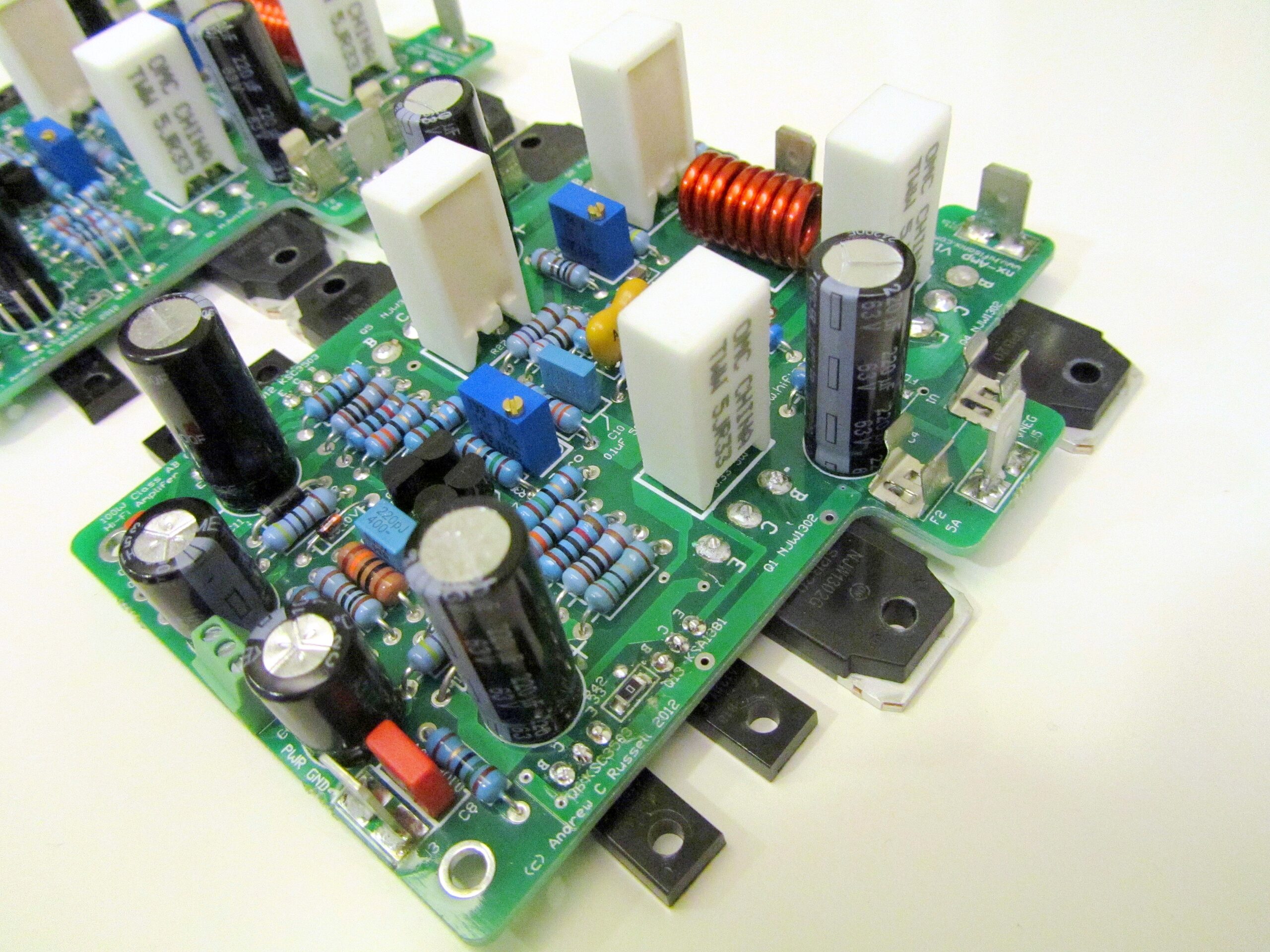
Hifisonix nx-Amplifier: A High Performance 100 W Class AB Current Feedback Amplifier
Originally published in December 2012.
This power amp design is based on the sx-Amplifier topology, but with the TIS and output stage re-configured for class AB operation, enabling it to deliver 100 W into 8 Ohms. I have kept the design very simple, retaining the CFA topology, providing a very wide -3 dB bandwidth of 570 kHz, high slew rates (140 V/us) and low distortion. Since it was first published in 2012, about 400 board sets have been sold world-wide (the sister sx and kx2 class A current feedback amplifiers have had combined sales of around 450 board sets). The nx-Amplifier is a perfect introduction to current feedback amplifiers, showcasing the topologies legendary open midrange, fantastic bass performance and delicate, silky top end.

Amplifier write up with circuit description, wiring diagram and construction details:- The-Ovation-nx-Amplifier-V2.10 (updated November 2014 to V2.0 PCB’s incorporating all feedback and updates). Please IGNORE the BOM in the build document and instead use this latest BOM, released in December 2021 that uses currently available semiconductors nx-Amp BOM December 2021
You can get a complete set of double sided THP Gold Plated V2.0 PCB’s for the above from Jim’s Audio on ebay here:
Hifisonix nx-Amplifier PCB Set
(2 off nx-Amplifier boards + 1 off PSU +Protect excl. shipping).
Here is a link to the diyAudio forum discussing this amplifier and the sx-Amplifier. If you have any questions, you can post them up here or on the diyAudio forum.
1. The nx&sx-Amp PSU board is a simple unregulated PSU board with no muting, output short circuit or DC offset protection. The only protection is the amplifier module fuses
2. . The nx-Amp_PSU+Protection board option couples an unregulated PSU with speaker muting, output short circuit protection and DC offset detection protection.
See the nx-Amplifier article above for details. If you have any questions, feel free to post your questions up here.
If you are a manufacturer, kit supplier or DIY shop, and you want to use the designs (circuit or PCBs) you need to contact me.
I’d be happy to hear your comments/feedback.
Notes and Addendums
1. Please note, there in no R2 on the PSU +Protect PCB or on the schematic although the BOM calls for it.
Comments
77 responses to “Hifisonix nx-Amplifier: A High Performance 100 W Class AB Current Feedback Amplifier”
Hello Kari,
sorry to hear you could not get me with email. You can get me at andrewc.russell(at)gmail.com. The bonsai(at)hifisonix.com is also working. Please replace the (at) with @ in both cases
To your question about replacing the 1302 and 1381 devices. I have not tried the ones you suggest, but looking at the data sheets, they look very good and an excellent match for the types I specified. Mechanically they are bigger than the TO3-P so you will just need to check that but I think it will be ok. The pin spacing is however the same.
If you go ahead with these, let me know how your build goes – any problems, feel free let me know.
Regards
Andrew
Hello from Finland! Can i use c5200/a1943 bjt’s for power devices, it’s hard to get orginal 3281 types, njw1302 is still available.
Ps I try to hit you with email but get response: The recipient server did not accept our requests to connect.
I use gmail and msn hotmail and get same response.Hello Raph, thank you for your kind words.
If you use a single PSU for the 4 channels, my recommendation is that you
1. only connect the 4 channels signal ground at the input. Make sure the signal ground on the input connectors does not touch or make any contact with the chassis – ie insulated
2. make sure that all the power cables and speaker cables are tightly bound together from each amp module to the PSU and ‘drop them off per the input signal cables as I describe below
3. run the input signal cables a bunch of 4, drop off to the first amp, then take the remaining 3 and drop off to the 2nd amp, remaining 2 to the 3rd amp, and th final 1 to the 4th amp
[Steps 2 and 3 above ensure the total loop areas between the modules are minimized]
4. I’d recommend you use a good quality screened transformer and remember to rotate the transformer to fund the noise null point.
5. from the PSU 0V, run a single cable to the chassis 0V. There must be no other 0V connection to the chassisRegards
andrew
Hi Andrew,
hope you are doing well!
I’m working on a kind of “hybrid” 5.1 design for a friend in which I could work in pure stereo and switch to 5.1 by powering up 2 additional channels + the center/bass one. As I really like my nx-amp (it is my day to day amplifier for the past last two years) I asked to my self if I could “simply” use 4 nx-amp + something else to achieve my goal. If I would go that way, do you think it’s better to go with 2 separate PSU for the 2×2 nx-amp or do you think it would be better to go with one bigger PSU (in which case I think it will be out of my knowledge/capability for now).
Thank you for any advice or warn concerning and best from France.
RaphHi Thomas, please feel free to send some pics!
Hi Bonsai,
Thank you very much for your replies. As I wrote on beginning my effort is focused to build nx-Amp. I decided to design and build my own PCB, also protection circuit is redesigned according my needs. I’m building this amplifier as dual mono block, with possibility to connect source via balanced and unbalanced line. Also grounding scheme is little bit resigned according topology used on Yamaha professional power amplifiers. Already I have manufactured two identical PCBs for power amplifier and I’m in process of design Input audio line receiver board based on THAT1200. I can send some pictures to you in case of interest.
BR,
TomasTomas,
no – you must not use the MJE types – low gain, non-linear Ix vs gain characteristic and high Cob. please see my earlier reply to you on this point.
Regards
Andrew
Hello Tomas,
those devices actually look quite good and the Cob is also ok.
Which amplifier are you building?
on the kx-Amp, you don’t need to have the gain grades matched – it will make no difference to the distortion performance. To be honest, I’ve built all my nx-Amp’s with unmatched gain grades as well without any problems. On the sx-Amp, you will get better distortion performance if you match the gain grades, but if you used mismatched devices, the amp will still work.
hope this helps
Regards
Andrew
Hello Bonsai,
Again it’s me. I was looking around available replacements for KCS3503 and KSA1381 on TIS (it is impossible to get them with same hfe classification/grade). I found similar transistors To126, which are available to buy NTE2509 and NTE2508. They have little higher Cob and Cre. Maybe this complementary pair is good candidate for original transistor replacement. Here is link to datasheet: https://www.nteinc.com/specs/2500to2599/pdf/nte2508.pdf . I would like to hear (read) your opinion.
Tomas
Hello Bonsai,
I’m collecting information and components to build up this nice amplifier. I have question about transistors KSA1381 and KSC3503. I’m unable to get them in my location with same Hfe classification. Can I replace them by MJE350 and MJE340 (of course selected pieces with same Hfe)?
Alfred, I haven’t specifically measured it, but its about 200-300.
Hello.
I am verry interested by this OVATION NX-AMPLIFIER ……
You have any Information about the Dampingfactor ?
Thank you.
Best Regards
AlfredJavier – this is good info for the other builders. Thanks for sharing.
Andrew,
Sure, no problem.
PDTA144ET,215 –> MMUN2113LT3G (OnSemi)
PDTC144ET,215–> SMMUN2213LT1G (OnSemi)
PDTA115ET,215–> DTA115EKAT146 (Rohm)I inspected the data sheets pretty closely and they appear to be the same in fit and function. Mouser had the Rohm part listed as a 100mA device but checking the datasheet, the output current is listed at 20mA, exactly the same as the Nexperia. Plenty of stock at Mouser on the substitutes. All the above Nexperia parts have fairly long lead times and they keep getting pushed out.
Thanks for the feedback Javier! do you have the part number you could share with us?
Hi Andrew,
Just wanted to give you a head’s up that last Fall I ordered some of the SMT parts. The Nexperia pre-biased transistors keep getting pushed out on delivery dates. Mouser now reporting 2020 for delivery. Ouch! I decided to put in some sweat equity and did my homework. I found comparable parts from OnSemi and Rohm in stock. So that should solve the problem.
Javier,
Any brand of 2N7002 will work – its just a general purpose mosfet switch – IIRC ON, Infineon etc all make them.
I think the electronics industry is going through one of its periodic ‘busy’ times (‘allocation’) so some parts may be a little short over the next few months – however, it will settle down again.
Regards
Andrew
Andrew, looks like certain SMD parts are getting harder and harder to chase down. There is a worldwide shortage of MLCC ceramic caps. I am scrambling right now to find stock on these parts and get them on order before stock dries up because lead times are very long.
Question – on the psu, how critical are the values of the 2n7002 from Nexperia? Stock is hard to find on the part you call out and I just want to sub an alternate before stock is gone on those. Thanks!
Andrew,
Ok, this makes sense. In fact, I believe you solved a mystery I had when I powered a tube/mosfet headphone amp with a toroid. The amp would hum and I had to play with orientation to eliminate it. I appreciate the help!
Hello Javier,
I just had a similar question from Anand. You could just go with the standard transformer for now and upgrade later. As I remarked to Anand, the radiated fields from the power supply in a class A amp are high because of the high standing currents. So, even at low output volumes, if you are not careful, you can get hum.Hi Andrew,
Thanks for the answers and being available to offer support on a design that’s been out for quite a while. Wonderful news on the driver transistors! I do have a question about the transformer. Antek no longer lists any xformers >400VA with a static shield. I assume if I buy an off-the-shelf version that the noise performance won’t compromise the noise level output of the amp too much. What is your experience with no shield/no belly band vs. one with the added noise protection? I guess I could spring for the Antek now and later follow up with a custom version that I can source here in the States with all the bells and whistles.
Hello Javier,
100 of each should definitely enough to be able to match Q8~Q11 transistors accurately enough.
To preserve your (precious) stock of 1381 and 3503, you can replace:-
Q12 with KSC2690A (NPN) and Q13 with KSA1220A (PNP)
These are actually better suited for the output driver role and it means you can keep your VAS devices for another future amp.
Good luck with your build – any more questions, feel free to ask.
Regards
Andrew
Hello Andrew,
I am finally getting around to building this amp. I’ve searched here and on the diyaudio forum but I’m not sure how many of each transistor I should buy to get reasonable matches. Is 100 each about right of Q8, Q9, Q10, and Q11? I’m not sure how many you had to measure to find the necessary matches.
I bought 8 each of the driver transistors several years ago because I heard they were really good. I will match as close as I can with my locky_z curve tracer. Those drivers are gold to me and after looking over other projects on diyaudio, I decided to commit to using the unobtainium ones on your amp.
Vlad,
ok – I can look briefly at your layout but of course there is a chance that I can miss something. Complete your layout and then send me a picture of the layout.
Regards
Andrew
Hello!
I would try to build the ovation nx amplifier, but I have a little problem: the case (and heatshink) I have for this project is 100mm tall and the pcb won’t fit in it. I want to redesign the pcb so iti will fi on my available heatshink and I want to know: are you available to help me with advices regerding the pcb layout? This is a high speed design so, I understand that the pcb tracing is a bit critical.
Thank you!Hello Al,
the ROUNDED end is the cathode. If you look carefully on your diode, you will see a band or light line – that’s the cathode side.
Regards
Andrew
Sorry I didn’t mention which boards.
The Ovation boards from Jim’s audio (Stanton). For instance on the underside of the power supply there are diodes (D4 – BAS21H) with the symbol I am unfamiliar with. I’m not sure which way to orientate the device with respect to anode and cathode.
Thanks for any advice.(On the boards the SMD diodes are symbolized as a broken box with one end rounded and the opposite end straight. Could you advise me what the orientation is for anode and cathode?)
Cheers,
Albert
Leave a Reply