Hifisonix nx-Amplifier: A High Performance 100 W Class AB Current Feedback Amplifier

Originally published in December 2012.

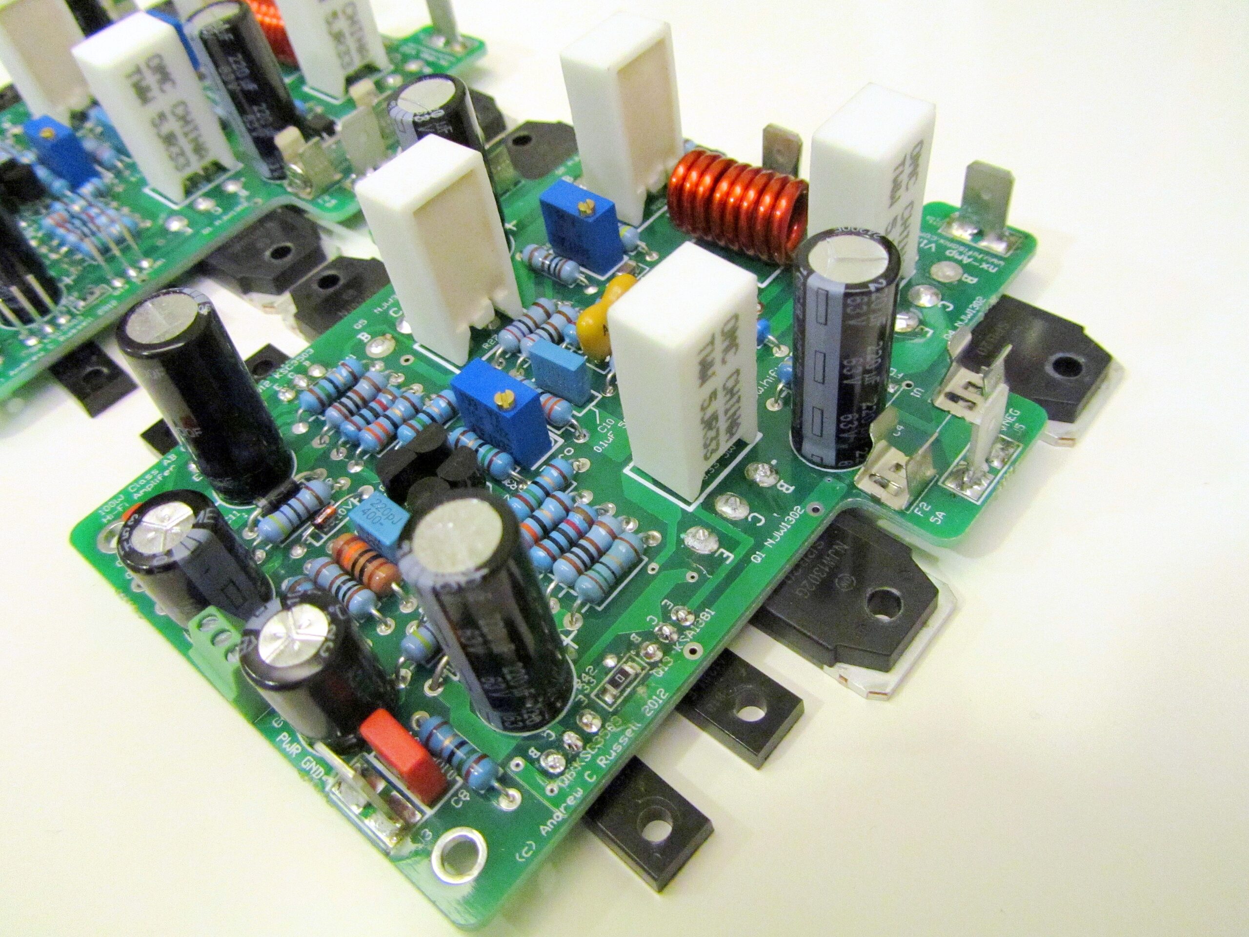
This power amp design is based on the sx-Amplifier topology, but with the TIS and output stage re-configured for class AB operation, enabling it to deliver 100 W into 8 Ohms. I have kept the design very simple, retaining the CFA topology, providing a very wide -3 dB bandwidth of 570 kHz, high slew rates (140 V/us) and low distortion.

Amplifier write up with circuit description, wiring diagram and construction details:- The-Ovation-nx-Amplifier-V2.10  (updated November 2014 to V2.0 PCB’s incorporating all feedback and updates).  Please IGNORE the BOM in the build document and instead use this latest BOM, released in December 2021 that uses currently available semiconductors  nx-Amp BOM December 2021

You can get a complete set of  double sided THP Gold Plated V2.0 PCB’s for the above from Jim’s Audio on ebay here:

Hifisonix nx-Amplifier PCB Set

(2 off nx-Amplifier boards + 1 off  PSU +Protect excl. shipping).

Here is a link to the diyAudio forum discussing this amplifier and the sx-Amplifier.  If you have any questions, you can post them up here or on the diyAudio forum.

1. The nx&sx-Amp PSU board is a simple unregulated PSU board with no muting, output short circuit or DC offset  protection. The only protection is the amplifier module fuses

2. .  The nx-Amp_PSU+Protection board option  couples an unregulated PSU with speaker muting, output short circuit protection  and DC offset detection protection.

See the nx-Amplifier article above for details.  If you have any questions, feel free to post your questions up here.

If you are a manufacturer, kit supplier or DIY shop, and you want to use the designs (circuit or PCBs) you need to contact me.

I’d be happy to hear your comments/feedback.

Notes and Addendums

1. Please note, there in no R2 on the PSU +Protect PCB or on the schematic although the BOM calls for it.
 

Comments

77 responses to “Hifisonix nx-Amplifier: A High Performance 100 W Class AB Current Feedback Amplifier”

  1. Anonymous says:

    Fabulous read – a fabulous write up with great photos n a meticoulsly detailed build – the magazines would pay $$$ for this sort of quality work – thanks for putting it out for the love of it !!!

  2. Anonymous says:

    Beauty in simplicity,

    Excellent design choices, beautiful . . .

    My sincere congratulation on Yours achievements 🙂

    Waiting for the PCB and BOM files … Will give it a try 🙂

    Thank You for all Yours effort and generosity to make this public available.

    With my best wishes to You Andrew,

    Andreas

  3. Neat design nicely implemented!
    Would be interested to hear about the PreAmp with tone controls when you have a moment. Are you thinking of including remote control as part of the spec?
    Peter

    • Bonsai says:

      Thanks for the interest Peter. I am actually working on a new preamp now with tone controls and a full set of line features. I will be posting up in a few months – still a lot of work to do though.

  4. MatteoS says:

    Congratulation.
    is it possible to extend power to 150+150w ?
    Do you have any comments to add regarding the sound quality and to compare with e-ovation amp?
    Thank you in advance.

    • Bonsai says:

      Hello Matteo,
      Thanks for your kind comments. You could probably raise the supply voltage to +-60V and it would still be ok. But, you would need to add another pair of output devices to handle the reactive load dissipation and also to minimize loading of the VAS stage.

      I have written in the back of the nx-Amp write up my feelings on the sound quality compared to the other amplifiers. This is a very smooth sounding amplifier with great bass performance. The e-Amp is a big complex amplifier aimed at delivering very low distortion (<10 ppm at 20 kHz @ 180 W into 8 Ohms). The e-amp will deliver about 250 W RMS into 8 Ohms and > 40 A pk into the load – so it is designed to drive any kind of speaker. I would describe the e-Amp as sounding forward and crisp. All four of my designs (sx, nx, e-Amp and Ovation 250) have very good imaging on my B&W 703’s – for me this is a critical aspect of an amplifiers performance.

      Additional Comment on 19th July 2013: I just realized that if you do raise the supply voltages, you will have to change Q9 andQ11 for higher voltage types. The original design used BC547C and BC557C which are 45V Vce max high hFE devices and too close for comfort to the specified max 50V supply railes of the nx-Amp. You can use BC546 and BC556 which have Vceo of 65V with the same high hFE that you get with the 547/557 types http://www.fairchildsemi.com/ds/BC/BC560.pdf

  5. Boban says:

    Hi Bonsai,

    im interested to build nx amp. I try to simulate, but something i do wrong. Can u please look: http://s19.postimg.org/f9are95ab/Screen_Shot_00039.jpg
    I get current trough VAS 68mA and gain is 18x. I use LT Spice.

    Regards,
    Boban

    • Bonsai says:

      Boban, yes a few other people picked up on this on DIYAudio.com.

      1. If your gain is simming at 18x it’s because you have included the 15 Ohm ground isolation resistor in your sim circuit. Short it out and the gain will be correct at 37x (=32dB).

      2. In the circuit, the front end buffer transistor load resistors are shown as 4.7k. This wrong – the correct value is 10k. Note that the PCB layout is correct.

      3. Further, if you measure a good working unit, the VAS current is actually higher than the sim suggests at 43mA (sim shows 28 mA). The reasons for this are the low value of the VAS transistor emitter degen resistors (15 Ohms) and the in accuracy of the VAS transistor models. A higher emitter degen value, say 27 or 33 Ohms will help to stabilize the VAS current, but in practice 15 Ohms works just fine which is where I have left mine.

      4. I will update the documentation in a few weeks to cover these points.

      5. For the time being, there is a very nice thread on DIYAudio.com under solid state called ‘sx&nx amplifiers’ where some forum members are building these amps. Here is the link http://www.diyaudio.com/forums/solid-state/236522-sx-amp-nx-amp.html

      Thanks for your feedback – I appreciate it.

  6. Dan says:

    Hello Bonsai, i was thinking to power this amp with a SMPS, do you think it’s ok ? Also What sensitivity your speaker have ?

    • Bonsai says:

      Dan, you could try this. Just make sure that the SMPS output is clean under load and there are no HF spikes. CFA amplifiers are not noted for their outstanding PSRR, so make sure the SMPS is well filtered.

      I am using B&W 703 speakers. They are specified at 89 dB.

  7. bimi says:

    I can not find Ovation nx-Amplifier V2.0_6.pdf file.

    • Bonsai says:

      bimi, yes another guy contacted me to tell me this already – but thanks for pointing out as well. The link to the article and the nx-Amplifier PCB Gerbers is broken – I will fix it on Thursday when I get back from my business travels.

      In the meantime, you can read about the sx-Amplifier 😉

      Thanks for your patience!

  8. Rafael R. Robles says:

    Sir,

    I’ve read a lot about your work especially the nx and sx at diyaudio and because of this I wanted to try myself to build the Ovation nx power amplifier. Just recently I have ordered the pcb’s at jim’s audio on ebay which still hasn’t arrived yet. Do you happen to have a worksheet (excel) file on ur BOM for the Ovation nx amplifier? It will make easier for me to order parts at Mouser and I will give you thanks for that.

    Any feedback will be highly appreciated.

    Raffy

    • Bonsai says:

      Hello Raffy,

      If you down load the PDF file from my website, the BOM is detailed at the back of the document.

      Hope you enjoy building and listening to your nx-Amp!

      Any questions just let me know. Please also post your questions on DIYAudio on the sx and nx thread.

      Regards

      Andrew

  9. Rafael R. Robles says:

    Thank you for the quick response. What I meant was an excel file that can be copied and paste into mouser which I think will make ordering parts much easier than typing them individually.

    I have just received the PCB’s which I ordered at jim’s audio and will now order the parts need for this build. Anyways any ideas on increasing the output of this particular amp? I know it can do 180w @ 4ohms as per your documentation but somehow it would be much better if you have ample power to drive low impedance and inefficient speakers such as magnepan’s or esl’s.

    Thank you for sharing your ideas and knowledge to the DIY world.

    • Bonsai says:

      Yes, I have the spread sheet. I will post it up tonight along with the Rohm cross reference data for the RETs (resistor equipped transistors).

  10. Vinnie says:

    Hello Andrew,
    I’m writing from Italy.
    First of all congratulations for the design of this accurate CFA. I experimented several times the incredible sound of this topology, due to the fact that me and a friend of mine built different versions of the Mark Alexander amplifier. The last version has a new layout, with a relay that is a standard one instead of the relay reed in the original design and the output stage with three pairs (per channel) of IR IRFP240/9240. This version is driving a couple of not-so easy-to-drive Magneplanar 2.5, instead of a good (but not so good if compared with MA CFA) Aragon 8008. A good result, I think.
    However I’m impressed for your paper, for your ability to design efficient PCBs and for your knowledge. That’s why I’m waiting for the PCBs bought from Jims Audio, and I will build and I will experiment different configuration of your superb amplifier.
    My first question is: I want to use a power supply of +35/-35 continuos (I have a toroidal transformer of 2X24 alternate): which resistors I should change (I thimk R18 and R19)? A value of 2,2k could be correct? Which other changement?
    Another question: you decided to use BC547/Bc557 instead of the usual BC550/Bc560, that is a no noise BJT: may I ask you why? Is it possible to use the BC 550/560 (I own hundreds of this BJT and I can select the best for VBE and hfe). A last paranoyd (from audiophile point of view) question: what do you think about using the supermatch couples SSM 2210/2220 or MAT02/MAT03 of PMI?
    Thnaks again, congratulations and … Happy New Year!
    Vinnie

    • Bonsai says:

      Vinnie, thanks for your kind comments – and best wishes for the new year as well.

      You can use BC560/550 without any problem.

      +- 35 V is quite low, so you are going to get a lot less power than with a +-50V power supply.

      I will take a look at the circuit tomorrow and leg you know what the resistor value changes are.

      Good luck with your project!

  11. rado says:

    I use 70V power supply ????When changing some resistance ???

    Thanks

    • Bonsai says:

      Radoslav, do you mean +- 35 Volt power supply?

      The front end Zeners and their associated bias resistos set the front end stage and TIS currents.

      For +-35V DC Supply R18 and R19 become 2.7 k Ohms

      For +-25V DC Supply R18 and R19 become 1.8 k Ohms

      I do not really recommend +- 25V DC rails – the output power will be severely curtailed – probably only 12~15 W into 8 Ohms.

  12. rado says:

    I think + – 70V ….

    Thanks

    • Bonsai says:

      Unfortunately that’s far too high for this design. The whole front end would have to change and the TIS stage would also need a redesign because of power dissipation issues.

      The maximum safe supply voltage is 50 V

  13. rado says:

    I use these PSMN4R4-80PS instead PSMN4R3-100PS

    thanks

    • Bonsai says:

      Hello Rado, you must only do this if your total power supply voltage from V+ to V- is LESS THAN 80 VOLTS. If it is above this,mother use the PSMN4R3-100PS.

  14. Anton Hendra says:

    Dear Mr Russel,
    Can I have the dual layer gerber file for Ovation nx-Amplifier.
    Thank You

  15. Vinnie says:

    Hello Andrew,

    I wrote you on december last year asking about youramplifier with CFA topologgy

    I bought two pcb sets from jim’s audio.

    My question is: it is possible to use one set to build the 15watts class A version? I read the schematics and I found the 100 watt class AB a bit more complicated. Which are the modofications adopted in the 100 watt class AB that I should ignore to use the double sided pcd alsp for the 15 watts class A?

    Thanks

    Vinnie

    • Bonsai says:

      Vinnie,

      yes, it could be adapted for sx-Amplifier. you would have to do the following

      1. link the base to the emitter of the driver transistors
      2. change the bias controller so they are the same as the sx-Amp
      3. change compensation capacitor to 220pF

      This should do it!

      Regards

      Andrew

  16. David says:

    Hello Bonsai,

    Firstly, thank you for making your designs available to the masses and providing such great documentation.

    I intend to construct the nx-Ovation amplifier but have a couple of questions.

    I have scoured the internet but am unable to find the KSA1381/ksc3503 in the same gain grade from a reliable source. Fairchild only seem to manufacture the KSA1381 in the E grade and the KSC3503 in the D grade. Do you have any suggestions/alternatives?

    Some years ago I built the Leach Low TIM amplifier and have been happy with it’s performance, do you have any views on how the nx-Ovation compares to the Leach in terms of sound.

    Thanks
    Best wishes
    David

    • Bonsai says:

      David,
      Firstly, thank you for your kind comments.

      WRT the transistors, it’s unfortunate that you cannot get the same gain grades. However, this will not stop your amplifier from working well and sounding good.

      I would replace the driver transistors with the improved (higher Ic rating, higher power and larger SOA) types below

      KSA1220A (this is a PNP)
      KSC2690A (NPN)

      Then, just use the 1381 and 1302 devices you can get for the VAS devices.

      Any other questions, let me know – good luck with your build!

  17. jack says:

    hello
    i read your very informative article on proper grounding/hum and if i understand correctly if the transformer is double insulate, no grounding is necessary. is this correct? if so then avel transformers are double insulated …………also im trying to find the gerbers on this amp.will they be up soon as i really want to get started on this fantastic build………thanks

    • Bonsai says:

      Jack, you must always ground DIY amplifiers. Registered commercial amplifier companies have to pass stringent certifications (e.g. UL Certification) to be able to ship double insulated products that DIY builders cannot do.

      Always earth (i.e ground) the chassis of your amplifier.

      For PCB’s please see the link in the nx-Amplifier write-up to ‘Jim’s Audio’ ebay store where you can buy ready made Double Sided THP Gold Plated PCB’s.

  18. jack says:

    Bonsai.

    ok thanks, ill make sure that all connections are properly grounded,

    thanks for the info regarding the PCBs,after i posted asking about the files,i realized that it was unnecessary.

  19. Sjoerd Smits says:

    Hi Andrew, I am going to build this amp coming winter. It has been referred to me by Struth on DIYAudio.com.

    My question is if I could exchange the 10Volt Zeners with these:
    https://www.hypexshop.com/DetailServlet?detailID=2014

    Ofcourse positive and negative ones. I think this will do much with the sound quality because this is very clean!

    Any changes need to be made if I put these on instead of the zeners?

    Thanks!

    Sjoerd

    • Bonsai says:

      Hello Sjoerd, I think the Zeners will be a much easier solution – and cheaper as well. The Zeners produce little noise in practice (3 to 5 uV wide band) and the decoupling gets rid of a lot of this.

      The Hypex products are very good – but I think they are really for a different application.

  20. Andrew says:

    Hi

    Great amp design which I can’t wait to try out. I don’t see the PCBs on ebay now. Do you know if they are still available?

    Andrew

    • Bonsai says:

      Yes, you can get them st Jim’s Audio – just follow the link on the 2 nd page of the write-up

  21. Anonymous says:

    in your specifications there is no damping factor , did you not measure it or perhaps left it out of the specs

    • Bonsai says:

      I did not measure or simulate it – but it’s between 100 and 200. High DF is not critical for great performance – the cabling and cross over make getting low damping favors in practice quite difficult.

  22. Hi,
    pls, advice if nx-Ampli can drive 2 ohm speakers (Apogee Duetta)
    Tks for support
    BR
    Damir

    • Bonsai says:

      Hello Damir,

      No – I would definitely not recommend it for 2 Ohm rated speakers. The reason is it only uses 2 output pairs so there is likely to be a dissipation problem. Secondly, it uses an EF2 output stage and not an EF3, so its likely that distortion will be higher than with a nominally 8 ohm rated load.

      The nx-Amplifier is certainly ok to drive conventionally rated 8 ohm speakers that have a normal low impedance dip in the upper bass region. Typically the speaker impedance dips to 3 (or in some rare occasions 2 ohms) between about 200 Hz and 400 Hz. You have a high impedance bump at the LF resonance point (50-100 Hz) and beyond 500 Hz the speaker impedance ruses due to crossover impedance increasing with f. As far as I know (but please correct me if I am, wrong), the apogees have a very low impedance right across the frequency response below about 500 Hz.

  23. Esa says:

    Hi,
    Just ordered pair of NX pcb’s to replace my Aleph 5 – build, for JBL 2225H duty class-AB is better choice IMO. My question is about psu, I have 2x30v 545va toroid reserved for this build, 30v is sufficient voltage to drive NX-amp properly?

    • Bonsai says:

      Hello Esa,

      Yes this will still work – you should get about 80 W RMS output. After you have built it, just check that the front end Zener diodes are each measuring 10V

  24. Esa says:

    Thanks Bonsai!
    One more stupid question; I have 2pcs of those trafos, so I could do 2 more channels. Is it possible to bridge this amp and how?

    • Bonsai says:

      Yes, you can bridge them. Note that if you bridge an amp, the calculated additional power is 4x the power non-bridged power. However, the output stages are only sized for 100W into 8 Ohms or ~180W into 4 Ohms. So my view is you can safely deliver about 150 Watt continuous with peaks of 200 Watts.

      If your source preamp uses a balanced output, then you simply take signal ‘hot’ to one channel and signal ‘cold’ to the other channel. You then use the XLR screen to make the signal return back to your preamp (normally this is connected to the amp chassis in a balanced input system – you have to change this for bridged operation). note you will need to modify the source so that the XLR screen is connected to signal 0V rather than the chassis. You must insert a 22uF 35V non-polarized cap on the input to each nx-Amplifier module.

      If you do not have a balanced output on your preamp, you will need to put an inverting stage with a gain of -1 (use for example a good quality opamp like a LME47910 or an NE5534) in front of one of the amplifiers.

      You will have to take very good care with the wiring to avoid any hum pickup with either approach.

      My personal view is that even with 30-0-30 VAC trafo, you will still get plenty of power . . .maybe no need to go to the trouble of bridging 😉

  25. Esa says:

    Hello Bonsai,

    Other projects have taken a lot of my time but now it’s time to start ovation nx build finally. I was wondering do you have most recent and complete bom in .xls form? It seems I can’t copy&paste from .pdf and it’s quite a job manually type everything to mouser IF you happen to have .xls saved somewhere? 🙂

    Thank you!

  26. Al "Rusty" Cantalini says:

    On the boards the diodes are symbolized as a broken box with one end rounded and the opposite end straight. Could you advise me what the orientation is for anode and cathode?

    Cheers,

    Albert

    • Bonsai says:

      Hello Al,

      which amp are you building? Can you give me a component reference number on the board?

  27. Al "Rusty" Cantalini says:

    Sorry I didn’t mention which boards.

    The Ovation boards from Jim’s audio (Stanton). For instance on the underside of the power supply there are diodes (D4 – BAS21H) with the symbol I am unfamiliar with. I’m not sure which way to orientate the device with respect to anode and cathode.
    Thanks for any advice.

    (On the boards the SMD diodes are symbolized as a broken box with one end rounded and the opposite end straight. Could you advise me what the orientation is for anode and cathode?)

    Cheers,

    Albert

    • Bonsai says:

      Hello Al,

      the ROUNDED end is the cathode. If you look carefully on your diode, you will see a band or light line – that’s the cathode side.

      Regards

      Andrew

  28. vlad says:

    Hello!
    I would try to build the ovation nx amplifier, but I have a little problem: the case (and heatshink) I have for this project is 100mm tall and the pcb won’t fit in it. I want to redesign the pcb so iti will fi on my available heatshink and I want to know: are you available to help me with advices regerding the pcb layout? This is a high speed design so, I understand that the pcb tracing is a bit critical.
    Thank you!

    • Bonsai says:

      Vlad,

      ok – I can look briefly at your layout but of course there is a chance that I can miss something. Complete your layout and then send me a picture of the layout.

      Regards

      Andrew

  29. Javier Galvan says:

    Hello Andrew,

    I am finally getting around to building this amp. I’ve searched here and on the diyaudio forum but I’m not sure how many of each transistor I should buy to get reasonable matches. Is 100 each about right of Q8, Q9, Q10, and Q11? I’m not sure how many you had to measure to find the necessary matches.

    I bought 8 each of the driver transistors several years ago because I heard they were really good. I will match as close as I can with my locky_z curve tracer. Those drivers are gold to me and after looking over other projects on diyaudio, I decided to commit to using the unobtainium ones on your amp.

    • Bonsai says:

      Hello Javier,

      100 of each should definitely enough to be able to match Q8~Q11 transistors accurately enough.

      To preserve your (precious) stock of 1381 and 3503, you can replace:-

      Q12 with KSC2690A (NPN) and Q13 with KSA1220A (PNP)

      These are actually better suited for the output driver role and it means you can keep your VAS devices for another future amp.

      Good luck with your build – any more questions, feel free to ask.

      Regards

      Andrew

  30. Javier Galvan says:

    Hi Andrew,

    Thanks for the answers and being available to offer support on a design that’s been out for quite a while. Wonderful news on the driver transistors! I do have a question about the transformer. Antek no longer lists any xformers >400VA with a static shield. I assume if I buy an off-the-shelf version that the noise performance won’t compromise the noise level output of the amp too much. What is your experience with no shield/no belly band vs. one with the added noise protection? I guess I could spring for the Antek now and later follow up with a custom version that I can source here in the States with all the bells and whistles.

    • Bonsai says:

      Hello Javier,
      I just had a similar question from Anand. You could just go with the standard transformer for now and upgrade later. As I remarked to Anand, the radiated fields from the power supply in a class A amp are high because of the high standing currents. So, even at low output volumes, if you are not careful, you can get hum.

  31. Javier Galvan says:

    Andrew,

    Ok, this makes sense. In fact, I believe you solved a mystery I had when I powered a tube/mosfet headphone amp with a toroid. The amp would hum and I had to play with orientation to eliminate it. I appreciate the help!

  32. Javier R Galvan says:

    Andrew, looks like certain SMD parts are getting harder and harder to chase down. There is a worldwide shortage of MLCC ceramic caps. I am scrambling right now to find stock on these parts and get them on order before stock dries up because lead times are very long.

    Question – on the psu, how critical are the values of the 2n7002 from Nexperia? Stock is hard to find on the part you call out and I just want to sub an alternate before stock is gone on those. Thanks!

    • Bonsai says:

      Javier,

      Any brand of 2N7002 will work – its just a general purpose mosfet switch – IIRC ON, Infineon etc all make them.

      I think the electronics industry is going through one of its periodic ‘busy’ times (‘allocation’) so some parts may be a little short over the next few months – however, it will settle down again.

      Regards

      Andrew

  33. Javier Galvan says:

    Hi Andrew,

    Just wanted to give you a head’s up that last Fall I ordered some of the SMT parts. The Nexperia pre-biased transistors keep getting pushed out on delivery dates. Mouser now reporting 2020 for delivery. Ouch! I decided to put in some sweat equity and did my homework. I found comparable parts from OnSemi and Rohm in stock. So that should solve the problem.

  34. Javier says:

    Andrew,

    Sure, no problem.

    PDTA144ET,215 –> MMUN2113LT3G (OnSemi)
    PDTC144ET,215–> SMMUN2213LT1G (OnSemi)
    PDTA115ET,215–> DTA115EKAT146 (Rohm)

    I inspected the data sheets pretty closely and they appear to be the same in fit and function. Mouser had the Rohm part listed as a 100mA device but checking the datasheet, the output current is listed at 20mA, exactly the same as the Nexperia. Plenty of stock at Mouser on the substitutes. All the above Nexperia parts have fairly long lead times and they keep getting pushed out.

  35. Alfred says:

    Hello.
    I am verry interested by this OVATION NX-AMPLIFIER ……
    You have any Information about the Dampingfactor ?
    Thank you.
    Best Regards
    Alfred

  36. Tomas says:

    Hello Bonsai,

    I’m collecting information and components to build up this nice amplifier. I have question about transistors KSA1381 and KSC3503. I’m unable to get them in my location with same Hfe classification. Can I replace them by MJE350 and MJE340 (of course selected pieces with same Hfe)?

    • Bonsai says:

      Tomas,

      no – you must not use the MJE types – low gain, non-linear Ix vs gain characteristic and high Cob. please see my earlier reply to you on this point.

      Regards

      Andrew

  37. Tomas says:

    Hello Bonsai,

    Again it’s me. I was looking around available replacements for KCS3503 and KSA1381 on TIS (it is impossible to get them with same hfe classification/grade). I found similar transistors To126, which are available to buy NTE2509 and NTE2508. They have little higher Cob and Cre. Maybe this complementary pair is good candidate for original transistor replacement. Here is link to datasheet: https://www.nteinc.com/specs/2500to2599/pdf/nte2508.pdf . I would like to hear (read) your opinion.

    Tomas

    • Bonsai says:

      Hello Tomas,

      those devices actually look quite good and the Cob is also ok.

      Which amplifier are you building?

      on the kx-Amp, you don’t need to have the gain grades matched – it will make no difference to the distortion performance. To be honest, I’ve built all my nx-Amp’s with unmatched gain grades as well without any problems. On the sx-Amp, you will get better distortion performance if you match the gain grades, but if you used mismatched devices, the amp will still work.

      hope this helps

      Regards

      Andrew

  38. Tomas says:

    Hi Bonsai,

    Thank you very much for your replies. As I wrote on beginning my effort is focused to build nx-Amp. I decided to design and build my own PCB, also protection circuit is redesigned according my needs. I’m building this amplifier as dual mono block, with possibility to connect source via balanced and unbalanced line. Also grounding scheme is little bit resigned according topology used on Yamaha professional power amplifiers. Already I have manufactured two identical PCBs for power amplifier and I’m in process of design Input audio line receiver board based on THAT1200. I can send some pictures to you in case of interest.

    BR,
    Tomas

  39. Raph says:

    Hi Andrew,
    hope you are doing well!
    I’m working on a kind of “hybrid” 5.1 design for a friend in which I could work in pure stereo and switch to 5.1 by powering up 2 additional channels + the center/bass one. As I really like my nx-amp (it is my day to day amplifier for the past last two years) I asked to my self if I could “simply” use 4 nx-amp + something else to achieve my goal. If I would go that way, do you think it’s better to go with 2 separate PSU for the 2×2 nx-amp or do you think it would be better to go with one bigger PSU (in which case I think it will be out of my knowledge/capability for now).
    Thank you for any advice or warn concerning and best from France.
    Raph

    • Bonsai says:

      Hello Raph, thank you for your kind words.

      If you use a single PSU for the 4 channels, my recommendation is that you
      1. only connect the 4 channels signal ground at the input. Make sure the signal ground on the input connectors does not touch or make any contact with the chassis – ie insulated
      2. make sure that all the power cables and speaker cables are tightly bound together from each amp module to the PSU and ‘drop them off per the input signal cables as I describe below
      3. run the input signal cables a bunch of 4, drop off to the first amp, then take the remaining 3 and drop off to the 2nd amp, remaining 2 to the 3rd amp, and th final 1 to the 4th amp
      [Steps 2 and 3 above ensure the total loop areas between the modules are minimized]
      4. I’d recommend you use a good quality screened transformer and remember to rotate the transformer to fund the noise null point.
      5. from the PSU 0V, run a single cable to the chassis 0V. There must be no other 0V connection to the chassis

      Regards

      andrew

  40. Kari says:

    Hello from Finland! Can i use c5200/a1943 bjt’s for power devices, it’s hard to get orginal 3281 types, njw1302 is still available.

    Ps I try to hit you with email but get response: The recipient server did not accept our requests to connect.
    I use gmail and msn hotmail and get same response.

    • admin says:

      Hello Kari,

      sorry to hear you could not get me with email. You can get me at andrewc.russell(at)gmail.com. The bonsai(at)hifisonix.com is also working. Please replace the (at) with @ in both cases

      To your question about replacing the 1302 and 1381 devices. I have not tried the ones you suggest, but looking at the data sheets, they look very good and an excellent match for the types I specified. Mechanically they are bigger than the TO3-P so you will just need to check that but I think it will be ok. The pin spacing is however the same.

      If you go ahead with these, let me know how your build goes – any problems, feel free let me know.

      Regards

      Andrew

Leave a Reply

Your email address will not be published. Required fields are marked *