Your basket is currently empty!
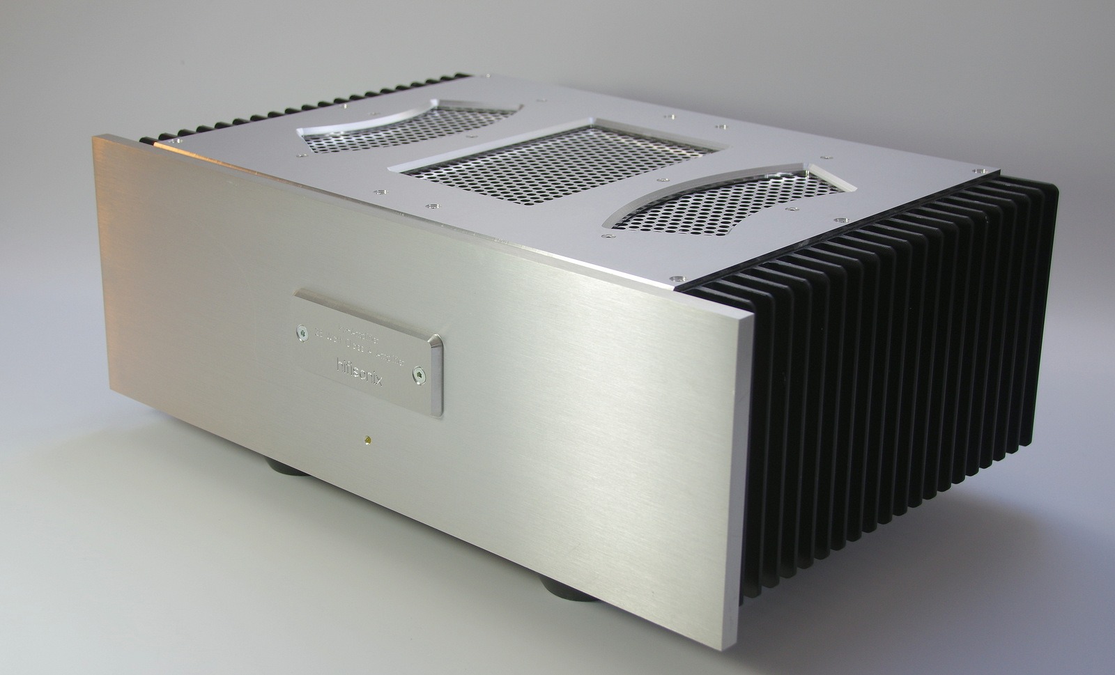
Hifisonix kx2 Class A Current Feedback Amplifier
The 15W RMS (28W peak class A) kx2-Amplifier offers outstanding noise and distortion performance and is specifically designed for driving high efficiency speakers in average to large listening spaces but also performs well driving more normal efficiency speakers in restricted listening spaces.
Click Here for the kx2-Amplifier Build Document
Click Here for the kx2-Amplifier BOM
Please note the kx2-Amplifier PCBs are supplied by Jim’s Audio. You can buy a set of two kx2-amplifier boards and a basic power supply board here:- kx2-Amplifier PCB Set
The kx2 features very low distortion (see the build doc linked to above for a full set of measurements) and uses TMC (‘transitional miller compensation’). By opening a jumper on the PCB, the compensation can be changed to standard Miller compensation which some people prefer. On the kx2, the output operating mode can be switched between class A, class AAB or class AB in similar fashion to its larger brother, the ax-Amplifier, by means of a 3-position toggle switch located on the underside of the amplifier just behind the front panel.
Careful attention to the PCB layout and routing of some tracks resulted in a dramatic 15 dB reduction in the measured noise floor. In class AB mode, the noise floor -120 dBr reference 15W RMS into 8 Ohms, and in class A mode -115 dBr 15 W RMS into 8 Ohms (inputs shorted to signal ground in both measurements).
The OPS bias is controlled with a single transistor servo that maintains the DC operating conditions to within 3% over the full operating temperature range (15C through to >60C).
The version you see in the image above was built in a housing that I originally purchased in Taipei when I lived there. I had a new top plate fabricated by Schaeffer AG in Germany in 2018. For UK builders, there is also the option in the UK of Meface Ltd, but the maximum panel thickness is 3mm.
Comments
50 responses to “Hifisonix kx2 Class A Current Feedback Amplifier”
Hello Nikola, thanks for your kind feedback. The page is now fixed – apologies for that.
Regards
Andrew
Hello Andrew,
Thanks for sharing such amazing design with the community!
I just placed an order of the PCBs from Jim’s Audio, although the documentation link is not valid https://hifisonix.com/wp-content/uploads/2022/11/kx2-Amplifier-25th-November-2022.pdfBest Regards,
NikolaHello Filip
1. The kx2 boards on Jims Audio are correct and 100% current
2. The PSU + Micro Ripple Eater board is not the latest version, but is useable. The latest version replaces the MJE15032 and MJE15033 (8A 250 V TO220 devices) with NJW1302 and NJW3281 15A 250V 200W devices and is therefore much more rugged. For the version you linked to on Jim’s audio, just replace the MJE devices with the NJW devices – that’s the only change.
3. You are correct – the PSU and ripple eater are combined onto 1 board so you only need 1 PSU + Mircro Ripple Eater for a stereo kx2-Amplifier.Any questions, let me know.
rgds
Andrew
Hello Bonsai,
I have a question regarding the kx2 boards at Jim’s store, here is the link :
https://www.ebay.com/itm/325227002647Are the PCBs up to date, or there are newer versions ?
Also, if I’m correct the following PCB is the PSU + Micro Ripple Eater board (2 in 1) ? In this case I don’t need separate PSU and Micro Ripple eater board ?
https://www.ebay.com/itm/325875316403Thanks in advance for your reply!
Regards!
Hi, the open loop gain is 91 dB and the loop gain is 63dB and the loop gain -3dB bandwidth is 12 kHz.
Hi Bonsai,
How much is the open-loop gain of the circuit?Georges, the Symphony was built nearly 10 years ago while I lived in Taiwan and I no longer have the Gerbers or the schematics. It really was just a personal project and I moved onto newer arguably better preamps although none feature tone controls. Sorry I cannot help you with this.
Kind Regards
AndrewHI Andrew
The ‘Symphony’ Line Preamplifier retains my attention due to the capability to drive tone control. Is that possible to get the complet description with BOM etc. How to get the PCB or gerber file to reproduce it on my own ?
Many thanks for your help.
Georges
Hi
Does the hifi2000 case 3U with heatsink 250mm or 300mm x 120mm suit for the kx2 on class A mode ?
Your help is appreciatedGeorges
Tanks Andrew, a
‘other question Is there a sonic difference between class a and Ab, stage depth, bass… When it’s move from a to Ab?Georges,
just use a transistor tester and put the closest matching gain KSA1381 and KSC3503 together in the same amplifier. so for example if you had 2 KSA1381 with gains of 220 and 180 and then 2 KSC3503 with gains of 280 and 310 then you would group them like this
220 and 310 together
180 and 280 togetherIf you have huge discrepancies then I’d buy a few more devices. for example, I had a whole bunch of 3503’s and 1381 all with gains between 180 and 300 but I had 1 device that had a gain of 50 – so I threw that one out.
Hope this helps
rgds
Andrew
HI
In the BOM , you wrote “Group the gains for each amplifier module”, can you please what the method to use ? Is that mean we have to buy a set of same transistors and do matching ?
Your sight is welcomeHello Viktor,
for the designs on this website, you buy the PCB’s from me (or Jim’s Audio), down load the BOM and order the parts from Mouser.com. For housings, you have to arrange that yourself but Modushop in Italy are a good source. Please also visit diyAudio.com for other designs etc.
Very few companies now provide full kits for audio gear – its almost all DIY from the ground up.
Hi all
Does anyone know where you can buy all the kits for the amplifiers, power supplies, etc. or do you have to buy each individual component yourself?
Is there a supplier who has all the necessary components in stock? That would of course be much easier.
Thanks very much!Jose, If you are building the sx or kx2 Amplifier, then you can use the KSA1381 (PNP) and the KSC3503 (NPN) in place of the 2690/1220.
Unfortunately, the 2690/1220 were discontinued just a few weeks after the kx2 was released. However, the 1381/3503 work very well.
What are the alternatives recommended to the KSC2690A/KSA1220A ?
Andrew,
Thanks for the reply, I have posted a photo on the DIYAudio.com kx2 thread.
Regards,
Filip.Filip
With 27VAC secondaries you will be at the upper limit of the design which is +- 35V DC. With your transformer I expect on load it will be 36-37VDC.
At this supply voltage you must run the Kx2 in class AAB (the amp will still need big heat sinks) or class AB which can be used with smaller heat sinks. Might be an idea to post a photo of your heatsinks up on the Kx2 thread on diyAudio.com
Regards
Andrew
Hello again,
1. What are the minimal/maximal values of the VPOS/VNEG voltages that can bed fed to the amp’s PCB voltage connectors?
I just got an AB class hand made dual mono amplifier with two 250 VA transformers with +-27V on the secondary, so I was thinking using it’s PSU and doing a dual-mono configuration of the kx2 amplifier. Does this sound OK to you ?
2. Related to this – when the amp is set to work in class AB (first 3-4 W in class A), do I really need these big heatsinks (like on the video) or I could reuse smaller ones from existing amp’ construction ? I know that the bigger the better, but maybe I could get away with this.
Regards,
Filip.Gregor, using a capacitor like this will not make any difference to the sound – it may make it worse. The reason is these large value film capacitors are physically big and therefore prone to noise pickup from the power supply.
I seriously recommend you go with the 22uF bipolar cap specified – these are very good and show zero (0) distortion passing AC signal as measured by an AP audio analyser (See Douglas Self comments on this in his books for example).
🙂
Thank you for the answer, but I had more in mind what producer maybe jantzen, mundorf.
maybe another one that will be better but not too expensiveHello Gregor, I used a 22uF 35 volt bipolar capacitor. The input impedance is 11k, so you you don’t want to use a cap value of less than 4.7 uF.
I have just finished the amplifier and before putting it into the housing, I wonder what input capacitor will be the best but not the most expensive, of course. what do you have
Hello Rene
1. yes – just solder C23 (220 uF 6.3V) as you have said in your post
2. change R4 and R5 from 10k to 1k
3. input capacitor and bleed resistor: yes the kx and kx2 amps will work without C4 and R7 (ie direct coupled) provided the source has NO DC offset. You must keep R24 (10k) – you cannot remove that.Here is the link to the version 1 doc – the original schematic is in there https://hifisonix.com/wp-content/uploads/2021/01/kx-Amplifier-Dec-2020.pdf
regards
Andrew
Hi there I already buildt the 2019 version , can I add the c23 simply by connecting plus to collector of the transistor and minus to Anode of d1? I also changed from 10 k ohm to 1 k ohm on the resistors , now I don’t have the Schenatic of version 1 handy right now , can you quote a link to that so I can tweak ? Thx 🙏 Rene ps: will it work without the input capacitor and without the bleeding resistor ?
Filip, The bias mode toggle switch has 3 positions: class A, class AB and class AAB
In class A the amp will supply c. 15W RMS (28 watts class peak) in pure class A. It will automatically transition to class AB if the output load demands more than 15W RMS output power. For example, if you are driving a 2 Ohm load, the first 15W RMS will be in class A, then the amp will transition to class AB and at full power can deliver about 90 Watts into the 2 Ohm load. Into 4 Ohms, the amp will deliver about 50W
In class AB the amp will deliver about 3-4W in class A and then everything above that in class AB. Into 4 Ohms the amp will deliver about 50W.
In class AAB, the amp will deliver the first 6-8W in class A and then the rest in class AB up to the same power levels above – ie 50W into 4 Ohms and about 90 into 2 Ohms.
Thanks for the information. Does the transition from A to AB/AAB happen automatically, for example when the power RMS exceeds 15W, or only using a dedicated switch ?
What would be maximal RMS power of the amplifier when using 8 Ohm speakers ?
Thanks in advance for answering!
Filip, no – all these PCB’s are handled by Jim’s Audio – you can get a set of 2 boards and a PSU board silk screened, double sided through hole plated for $24.99 – link per the sx-Amp page
Hi,
Do you offer gerber/drill files like for the SX amp ?
Regards,
Hello Andrej, that will work very well.
Hi.
I have a plan to use one Simple Ripple eater PSU per kx2 channel at +-35V voltage in AAB operation mode. Can I use 2×15000 uF 40V capacitors per channel or should I increase capacitance?
br
Andrej
Hello Andrej
100mm x 115mm
You can orient the PCB either way.
Hi.
What is minimal height of heatsink to accommodate kx2 amplifer?
br
Andrej
Yes, you can do that as long as they give the same voltage as the Zeners.
Hi Andrew,
What can you say about replacing BZX55B10 (D4, D5) with LM4040DIZ-10?
Best regards,
NicksonHello Nickson,
you have spotted an error in my document! Thank you for pointing that out. I will update the document tonight.
Regards
Andrew
Hi Andrew,
Is the phasing of the windings on page 29 shown correctly?
Best regards,
NicksonHi Andrew,
During the next month or so I will try it. I will order some BC517 next time I order parts.
There is no hurry. It was just an idea.BE/Claus
Clause, it’s not that easy. Although the bias current error term could be removed using a Darlington, the actual Vbe voltages are quite critical.
You could try it as an experiment and see if it works.
I will relook at the equation and replace the Vbe terms with the semiconductor junction formula which includes current density, temperature etc ie it is more fundamental that the simple voltage expression I’ve used.
Hi Andrew
Regarding the darlington proposal, I was looking at BC517. This transistor has a HFE of min 30000 and VCE saturation is <1V at 10mA Ic. VBE at 10mA is app. 1.1V. The pinout is the same as BC457 so if D1 was shortet voltages would be pretty close the present setup, and implementation might be quit simple.
The equation on page 18 can more or less disregard error voltage Q7 if the HFE is 30000. Error voltage would be in the order of 5-10mV.Of course this is just an idea, and the present setup you have done works really fine on the new KX2 boards. I have rebuild the KX amp with the new kx2 boards and noise and distortion is very good. (noise app -93dBV and -95dBV A weighted.. Distortion is bang on what you show in your presentation.
BR Claus
Hello Philippe,
I had a similar question from another builder. You can change R25 to 22 Ohms without any problems. You can also try 33 Ohms – I have not tried this, but it should still be ok. If you have a signal generator and a scope, you can check the square wave response to make sire it is not suffering from any overshoot at the lower gain.
for gains much lower than this (about 14x with R25 = 33 Ohms), I would suggest you use an attenuator in the front end. If you want to reduce gain below 14x, let me know and I will make a suggestion for you – the input filter will need to be adjusted.
regards
andrew
Hello Claus, thank you for your suggestion. Actually I have not considered that – it might be something I will explore if I do another class A amp.
What I would say to you though is that the currents and voltages around the bias controller are quite critical. In the kx2 amplifier, on slide 18, you can see the formula for the bias controller which is the same for the kx-amp – it has a lot of factors so you have to be quite careful. If I do use this approach, the circuit would have to be recharacterized to make sure it would work across many builds – same as the current circuit.
Regards
andrew
Hello Andrew
Thanks for the new design.
One question: is it possible to reduce gain with R22 = 22 instead R25 =15 (as it is in the KX amplifier) ?
Pspice tell me that it’s Ok but il’s better to be sure.
For users with an active preamp, it’s sometimes a very good solution.Thanks
Philippe
PS: my KX amplifier is working nicely in class A mode (very good sound and no noise)
Hi Andrew
Did you consider replacing Q7 and and D1 with a darlington transistor? If high hfe is important it will provide high current gain, Would that work?
BR
Claus
Thanks Claus – I will check it out tonight – appreciate your feedback.
Regards
Andrew
Hi Andrew
I noticed that Q7 in the schematic is listed as BC560/BC547. BC560 is a PNP type, but the schematic shows a NPN. I guess you mean BC550. I guess just a small typo!
BR/ClausHello Claus, glad you are still enjoying the sound of your kx-Amplifier. I think the kx2’s will be less troublesome to build and offer significant improvements in noise and lower distortion.
Regarding your question about speaker back EMF – I will specifically talk about feedback amplifiers, which the kx and kx2 (sx and nx as well) are. The amplifier does not care about the back emf. Due to the action of the front end error amplifier (same BTW for both CFA and VA), it simply looks to make sure that the divided down output voltage after the feedback network the -input is the same as the +input. If the amp is seeing back EMF of opposite polarity, it will adjust the output to ensure +input = -input. If the back EMF is the same phase, it simply again adjusts to make sure + input = -input. In order to ensure accurate drive of the speaker under these conditions, all that is important is that the OPS can handle the signal current +- any back EMF related current. On the kx and kx2 amplifiers there is no current limit circuit and the only protection is the fuses – you can short the output and the fuses will pop, but the OPS transistors will not fail since they are running at about 15% of rated Vceo). The short term repetitive peak current the OPS can deliver is about 10 amps, more than enough to deal with any back EMF issues given the supply rails in class A (+-28V typically).
Hi Andrew,
I am very pleased with my KX amplifier and after some rebuilds on the input stage I ended up with a design quit close to your new KX2 design. I have ordered some new KX2 PCB’s and will replace the PCB’s in time since the present KX PCB’s are a bit messy.
One question. I am a bit confused about current gain in output stages and how much current is needed to control a speakers EMF kickback. Bent Holter from Hegel claim that normal feedback is a problem and will not control speaker EMF correctly. My understanding is that you just need enough current capabillity in the amplifier. Do you have any experience with speaker EMF and how much peak current is needed?
BR/Claus
Dennis, the kx-Amp is still low distortion and low noise – you won’t hear hum with your ear against the speaker if you build and wire it up correctly. However, the kx2 is a better amp – measured lower noise and lower distortion.
I will certainly be here to help you get the best out of your kx-Amp if you decide to go ahead with it.
Hi,
I just bought 2 pair of kx amplifier pcb’s and parts. Is it better to take my loss and buy the kx2 pcb’s?
Best Regards,
Dennis
Leave a Reply