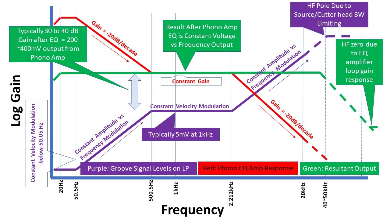
The diagram above summarizes the interaction of the cutting head response (purple) and the playback EQ (red) which produces the final flat response (green). Note that the cutting head and the phono pickup (cartridge) are velocity transducers and therefore the cartridge output rises at 20 dB/decade if the record groove is cut at constant amplitude.
Click here to buy a set of 2 Inverse RIAA PCB’s over in the shop
Designing and engineering RIAA equalizers demands a clear understanding of the signal chain requirements during the development process. Once components have been committed to a prototype PCB however, testing is required. Presented here is a simple Inverse RIAA Network, or IRN, that allows testing to be quickly and effectively done.

It is important that the RIAA equalizer response is accurate across the audio band (20 Hz to 20 kHz) and also well behaved beyond that. The usefulness of this simple tool can be gauged by the fact that, after building an RIAA EQ amp based on a design published by one of the foremost exponents of the art, testing revealed that whilst its sine wave response conformity from 20 Hz to 20 kHz was exemplary, the gain at 500 kHz was 8 dB higher that at 20 kHz, which manifest as overshoot on the square wave tests. Some simple mods to the RIAA network resolved the problem, and the response was then flat out to ~50 kHz, after which it dropped off ultimately approaching at 20 dB/decade at 200 kHz
Here is the article: Accurate Inverse RIAA
Pictured below is the conformity of a high performance phono amp using the IRN. The reading was taken with a QuantAssylum 401 measurement DAC/ADC set to 20 to 100 kHz display bandwidth sampling at 24bit/192 kHz.

Above: 20 Hz to 100 kHz frequency sweep response of RIAA amplifier fed through the IRN
Note in the picture above, the drop off in response below 100 Hz is due to the analyser response, and not the RIAA equalizer which is flat down to 20 Hz (rumble filter switched OUT).
The scope screen shots that follow (which are for the same RIAA amplifier) show how easy it is to test an RIAA EQ amp using just an IRN and a square wave stimulus. In the first picture, we see the performance at 20 Hz. The waveform tops/bottoms show a small amount of slope which is caused by a slight roll-off at 20 Hz (around 0.3 dB in this particular design).
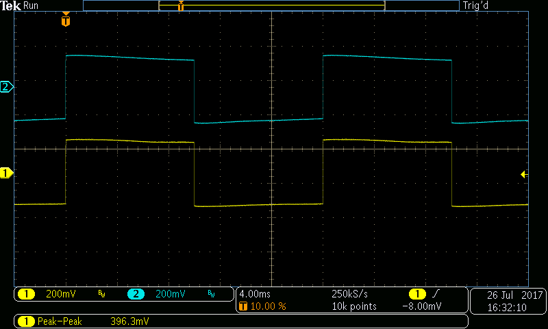
Above: RIAA EQ response to a 20 Hz square wave input stimulus fed via the IRN.
The shot below is for a 2 kHz square wave input stimulus. Since the square wave stimulus contains harmonics that are accurately amplitude related to the 2 kHz fundamental, this result implies that the response is accurate to at least 10 kHz (5th harmonic). The amplitude of the harmonics beyond 10 kHz is low, and therefore it is difficult to infer a high degree of accuracy above this frequency. Testing therefore has to take place at higher stimulus frequencies to confirm this.

Above: RIAA EQ output with a 2 kHz input stimulus fed via the IRN.
The shot below is for a 20 kHz square wave stimulus. The response is still remarkably good and in accordance with the results shown in the frequency sweep shown earlier. Since there is slight rounding of the edges, we can infer that the response has started to drop off above about 50 kHz.

Above: The response of a high conformity RIAA stage to a 20 kHz square wave input stimulus via the IRN.
Finally, the plot below shows the performance with a 50 kHz stimulus. The edges are rounded showing that the response is dropping off in a controlled manner (i.e. no overshoot or HF response anomalies) in accordance with the design requirements.

Above: RIAA EQ amp with 50 kHz square wave input stimulus fed via the IRN.
Leave a Reply